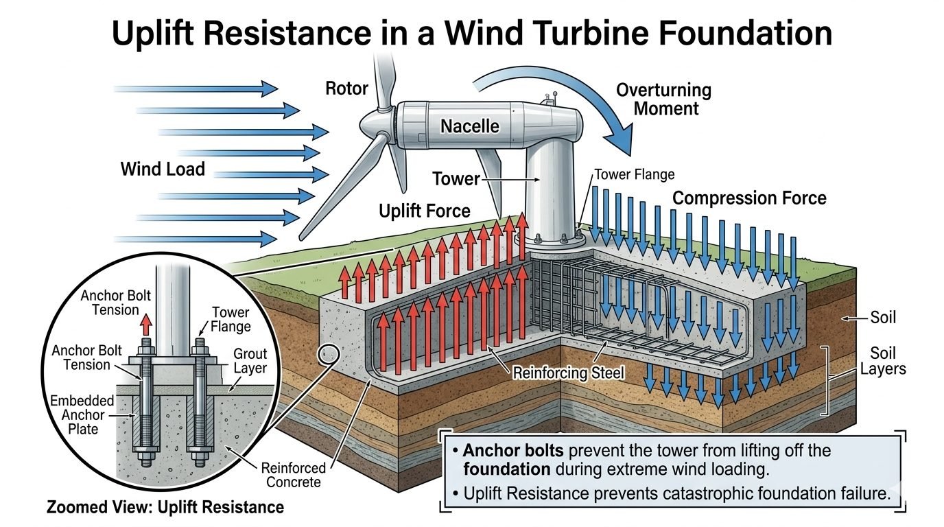
Wind Turbine Foundation Uplift Mechanics and Anchor Bolt Tension Design
In my two decades of heavy industrial structural engineering, few challenges match the relentless cyclic fatigue imposed by wind turbine generators. When severe atmospheric gusts strike the rotor and nacelle, they generate massive horizontal shear forces coupled with a staggering overturning moment at the tower base. As this moment pivots across the base flange, one side of the circular foundation experiences intense compressive stress while the opposing side undergoes severe uplift.
This uplift tendency threatens to tear the tower base directly off its concrete pedestal if not meticulously countered by deep anchor bolt networks. Through careful application of ASME structural guidelines and reinforced concrete design codes, I ensure these high-capacity anchoring systems remain safely within elastic deformation limits throughout a 25-year operational design life.
Key Engineering Takeaways
- Overturning moments translate directly into localized tensile forces on windward anchor bolts.
- Embedded anchor plates distribute concentrated bolt loads deep into the reinforced concrete foundation mat.
- Fatigue and preload relaxation require rigorous stress checks under extreme dynamic wind regimes.
Wind Induced Uplift Forces and Structural Mechanics
Aerodynamic Force Translation to Foundation Basements
The primary driver of wind turbine foundation uplift is the aerodynamic drag acting on the rotating blades and stationary nacelle housing. This force acts at the hub height, creating a massive lever arm above the foundation interface. The resulting overturning moment is calculated as the product of the total lateral wind force and the hub height, plus the vertical shear components.
When this moment is transferred down the tubular steel tower, it exerts a linear strain distribution across the foundation flange. The windward side of the flange tries to lift, while the leeward side presses down into the soil. To prevent catastrophic rocking or foundation pull-out, the mass of the concrete gravity base combined with the tensile capacity of the embedded anchor bolts must exceed the applied uplift force by a defined safety margin.
Core Engineering Calculation Steps for Uplift
- Calculate base shear (V) and overturning moment (M) using gust effect factors from ASCE 7.
- Determine the neutral axis and maximum bolt tension (T_max) using elastic section properties of the anchor circle.
- Apply load factors for dead load (resisting) and wind load (overturning) per ACI 318 strength design requirements.
Anchor Bolt Tension and Embedded Plate Behavior
Managing peak tensile loads requires a sophisticated understanding of load transfer from the high-strength steel anchor rods into the surrounding concrete matrix. As the windward flange lifts, individual anchor bolts stretch elastically, mobilizing the entire embedded anchorage assembly. The anchor plate, positioned near the bottom of the concrete pier, acts as a load-spreading mechanism.
Without this embedded plate, high point stresses would cause premature concrete breakout cone failure. The concrete cone breakout strength is evaluated carefully under ACI 318 Chapter 17 provisions, factoring in edge distances, cracking states, and supplementary reinforcement. In my designs, I always verify that the concrete tensile capacity matches or exceeds the ultimate yield strength of the steel anchor rods.
Critical Design Warning: Fatigue and Preload Loss
Wind turbine anchor bolts experience millions of cyclic tension reversals over their operating lifetime. Inadequate bolt preloading can lead to micro-gapping at the base flange, accelerating fatigue crack initiation and causing sudden bolt snapping. Always specify rigorous hydraulic tensioning protocols and inspect preload values during scheduled maintenance intervals.
Reinforcing Steel and Foundation Soil Interaction
Beyond the immediate anchor assembly, the entire reinforced concrete foundation mat and surrounding soil layers play a vital role in resisting uplift. The dead weight of the octagonal or circular concrete gravity base provides the first line of defense against overturning. However, for modern multi-megawatt turbines on soft soils, gravity alone is insufficient, requiring piled foundations or rock anchors.
The reinforcing steel cage inside the foundation must be detailed to transfer bending moments from the central pedestal outward to the perimeter of the mat. Shear reinforcement, including stirrups and headed bars, prevents diagonal tension failure in the thick concrete sections. Comprehensive geotechnical modeling ensures that passive soil resistance and friction beneath the mat are correctly integrated into the global stability matrix.
Advantages
- Provides high tensile resistance against extreme overturning moments.
- Allows precise leveling and alignment of the tubular steel tower base flange.
- Distributed anchor patterns prevent localized stress concentrations in the concrete mat.
- Readily inspectable post-installation via torque checks and ultrasonic testing.
- Complies fully with established ASCE and ACI design frameworks.
Disadvantages
- Susceptible to high-cycle fatigue cracking under fluctuating wind regimes.
- Requires meticulous installation tolerances to avoid uneven load sharing among bolts.
- Vulnerable to corrosion if moisture infiltrates the base joint and grout layer.
- Complex post-tensioning procedures demand specialized hydraulic tooling and expertise.
- Cost-intensive material specifications for high-grade alloy steel anchor rods.
Onshore Utility-Scale Wind Farms
Large multi-megawatt onshore wind turbines installed in high-wind regions rely heavily on massive gravity-spread foundations anchored by high-strength steel bolts. These installations must withstand severe atmospheric turbulence and wind shear profiles dictated by rough terrain and complex topography.
Offshore Fixed-Bottom Monopiles
Offshore transition pieces connected to large diameter steel monopiles utilize extreme-capacity bolted flange connections. The combined action of wind and wave overturning moments creates severe cyclic uplift, requiring rigorous corrosion protection and high-preload tensioning strategies.
Complex Mountain Ridge Installations
Ridgeline wind projects experience severe wind acceleration effects and erratic gust structures. Foundation engineers must design specialized rock-anchored socket foundations where conventional gravity bases are unfeasible due to shallow soils and extreme overturning forces.
Repowering Legacy Wind Assets
Upgrading older wind turbine sites with modern, larger-capacity turbines often requires evaluating existing foundations. Engineers perform detailed uplift and fatigue re-assessments to determine if legacy anchor bolt arrangements can safely accommodate the increased overturning moments of new rotors.
Wind Turbine Foundation Design Parameters and Force Allocations
Foundation design for utility-scale wind turbines requires precise quantification of aerodynamic thrust, rotor-nacelle assembly overturning moments, and dynamic cyclic load distributions. As an experienced piping and structural engineering consultant, I evaluate these structural interfaces using rigorous regulatory frameworks established by ASME and the American Concrete Institute. The following engineering data table outlines the core mechanical and geometric parameters governing wind turbine tower foundation stability, anchor bolt tensioning thresholds, and factored load combinations.
Engineers must meticulously cross-reference these operational variables against geotechnical soil reports and site-specific extreme wind profiles to prevent premature fatigue failure or progressive concrete degradation. Every parameter listed below directly influences the magnitude of the overturning moment transmitted through the tower base flange down to the embedded anchor ring assembly.
| Design Parameter | Typical Range / Value | Governing Standard | Engineering Significance |
|---|---|---|---|
| Extreme Wind Speed (V_ref) | 45 m/s to 70 m/s (50-year return) | ASCE 7 / IEC 61400-1 | Establishes baseline lateral wind pressure and maximum aerodynamic thrust loads on rotor. |
| Overturning Moment (M_ot) | 40 MN-m to 180 MN-m | ISO 19901-2 | Drives eccentric pressure distribution under base slab and maximizes bolt tension. |
| Anchor Bolt Preload (T_p) | 0.6 to 0.7 of Ultimate Tensile Strength | ASTM A615 / A354 | Mitigates cyclic fatigue damage and prevents joint separation during operational gusts. |
| Concrete Compressive Strength (f’c) | 35 MPa to 55 MPa (Minimum) | ACI 318 Chapter 19 | Resists extreme bearing pressures and ensures reliable bond strength for embedded anchor plates. |
| Foundation Embedment Depth | 2.5 m to 5.0 m below grade | ACI 336 / AASHTO | Provides passive soil resistance and rotational stability against massive overturning moments. |
Note: All values must be factored using ultimate limit state (ULS) load combinations before calculating individual anchor bolt stress cycles.
Technical Mapping & Specifications Matrix
Complex offshore and onshore wind turbine foundations integrate multiple structural sub-systems that must operate harmoniously under severe environmental loading. To assist design engineers and project managers in standardizing terminology and regulatory compliance, I have compiled this comprehensive entity mapping matrix. This matrix correlates structural components with their primary analytical functions, material specifications, and governing codes.
Proper coordination across these entities eliminates interface conflicts between the tower manufacturer, civil foundation contractor, and geotechnical engineering consultants. Review every mapping category carefully to ensure complete structural continuity from the nacelle down to the deep soil stratum.
| Structural Entity | Acronym / Symbol | Material / Parameter Specification | Governing Standard Code |
|---|---|---|---|
| Rotor Nacelle Assembly | RNA | Composite blades, structural steel mainframe, cast iron hub | IEC 61400-1 |
| Tower Flange Connection | TFC | Forged alloy steel (ASTM A709 Grade 50 / EN 10025 S355) | ASME BPVC Section VIII |
| Embedded Anchor Ring | EAR | High-strength structural steel plates with welded shear studs | AWS D1.1 Structural Welding |
| Reinforced Concrete Pedestal | RCP | High-performance concrete with epoxy-coated reinforcing rebar | ACI 318-19 |
| Geotechnical Soil Interface | GSI | Compacted granular backfill and dense bedrock strata | ASTM D1587 / D2166 |
Reference: Entity definitions align with international wind energy harmonization initiatives and standardized structural nomenclature.
Wind Turbine Foundation and Anchor Bolt Verification Checklist
Ensuring absolute structural integrity against extreme wind-induced uplift forces requires a rigorous, multi-stage quality assurance protocol during construction, tensioning, and commissioning phases. In my field engineering practice, I rely on structured verification frameworks to catch discrepancies before tower erection begins.
The following checklist synthesizes critical inspection milestones mandated by ACI 318 and ASME PCC-1 guidelines. Site engineers and quality inspectors must verify each item sequentially to certify that the foundation can safely transfer cyclic overturning moments and anchor bolt tension without structural distress.
Site Inspection & Quality Control Protocol
-
1. Subgrade Compaction & Bearing Verification: Inspect excavation base to ensure soil bearing capacity meets or exceeds structural design drawings in accordance with ASTM D1556 density testing standards.
-
2. Reinforcing Steel Placement & Clearance: Verify rebar size, spacing, and concrete cover thickness for both top and bottom foundation mats per ACI 318 specifications to prevent premature corrosion.
-
3. Anchor Cage Alignment & Leveling: Check anchor bolt template alignment, vertical plumbness, and embedment depth tolerances using calibrated optical leveling equipment prior to concrete pouring.
-
4. Concrete Pouring & Curing Monitoring: Monitor concrete slump, temperature, and cylinder break tests at 7 and 28 days to confirm target compressive strength (f’c) is fully achieved before load application.
-
5. Bolt Tensioning & Torque Calibration: Execute controlled hydraulic tensioning of anchor bolts following ASME PCC-1 guidelines, verifying final preload values with calibrated load cells.
Completion of every checklist item must be formally documented in the project quality dossier. Signed verification sheets protect asset owners and validate structural design assumptions against extreme environmental weather events.
Field Case Study: Remediation of Wind Tower Uplift and Flange Gapping
During routine structural inspections of a 3.0 MW onshore wind farm experiencing severe seasonal windstorms, maintenance personnel discovered audible mechanical clicking and minor grout cracking at the tower-to-foundation interface ring. Detailed structural auditing revealed that inadequate anchor bolt preloading combined with cyclic overturning moments had induced repetitive flange gapping and progressive bolt fatigue.
Problem Analysis: Extreme Wind Uplift & Flange Separation
The wind turbine foundation suffered from severe structural vulnerabilities caused by extreme aerodynamic overturning moments and inadequate initial bolt tensioning protocols.
- Extreme wind gust velocities exceeding 38 m/s generated cyclic overturning moments that repeatedly lifted the tower base flange off the concrete pedestal surface.
- Original anchor bolt preloads had relaxed by 22 percent over two years of continuous operation due to dynamic vibrational settlement and inadequate thread lubrication.
- Tensile stress peaks during windstorms exceeded the endurance limit of standard carbon steel fasteners, initiating micro-cracks in several anchor shafts.
- Cyclic pumping action forced moisture into the unsealed interface gap, accelerating localized corrosion and degrading the underlying non-shrink grout layer.
Engineering Outcome: Successful Remediation and Preload Optimization
Implementing a comprehensive engineering retrofit and rigorous retensioning program successfully restored structural integrity and eliminated all uplift fatigue risks.
- Replaced all degraded fasteners with high-strength alloy steel anchor bolts conforming to ASTM A354 Grade BD specifications.
- Applied hydraulic tensioning tools to achieve a verified preload equal to 70 percent of ultimate tensile strength, strictly following ASME PCC-1 appendix guidelines.
- Injected high-performance epoxy grout beneath the base flange to eliminate void spaces and restore uniform compressive load transfer to the concrete pedestal.
- Installed continuous digital strain sensors on critical anchor bolts to provide real-time remote monitoring of tension fluctuations during future extreme weather events.
This case study underscores the critical importance of maintaining proper anchor bolt tension and verifying foundation design assumptions against real-world wind loading profiles. Proactive engineering intervention prevents catastrophic structural failure and ensures long-term operational safety.
Frequently Asked Engineering Questions
How do extreme wind loads generate uplift forces on turbine tower anchor bolts?
- Horizontal aerodynamic thrust acts at the hub height to multiply the overturning lever arm.
- The tower base flange transfers eccentric axial loads directly to the embedded ring of tension bolts.
- Anchor bolts stretch elastically, pulling against the buried embedment ring to prevent base separation.
What design standards govern concrete embedment and tensile stress for anchor bolts?
- Calculations must account for concrete pullout failure cones radiating from embedded anchor plates.
- Tensile stress areas must incorporate thread reduction factors per ASME structural bolting guidelines.
- Fatigue amplification factors apply due to millions of cyclic wind reversals over the 20-year turbine design life.
How does foundation self-weight mitigate overturning moments from extreme wind?
- Concrete gravity mass creates a stabilizing downward restoring torque countering the aerodynamic overturning moment.
- Soil overburden resting on widened foundation flanges adds substantial dead weight resistance against uplift.
- Base sizing iterations adjust pad geometry until edge soil bearing pressures remain fully positive under extreme gusts.
What causes fatigue damage in wind turbine tower anchor assemblies?
- Turbulent wind gusts create rapid, cyclical tension spikes on windward anchor studs.
- Inadequate initial pretensioning allows joint gapping, accelerating impact fatigue and thread stripping.
- Corrosion fatigue mechanisms interact with cyclic mechanical stresses in aggressive coastal environments.
How do geotechnical parameters influence deep foundation uplift resistance?
- Skin friction along micropile or drilled shaft perimeters adds significant pullout resistance.
- Soil cone breakout resistance calculations depend on effective soil unit weight and internal friction angles.
- High water table conditions reduce effective soil overburden weight, requiring larger foundation footprints.
Field Recommendation
Based on decades of industrial structural design experience and forensic evaluations of wind turbine foundation failures, I advise applying the following rigorous protocols during detailed engineering and site installation:
- If soil borings reveal high groundwater tables or low cohesion soils, mandate deep micropiles or extended gravity base flanges immediately to counteract buoyancy and reduced soil overburden weight during extreme wind uplift events.
- When specifying high-strength anchor bolt cages per ASME standards, always enforce ultrasonic post-installation testing to verify zero void formation in the deep concrete embedment zone around embedded anchor plates.
- If extreme seismic zones overlap with high wind regimes, design the foundation concrete with dual-reinforcement mat layers to simultaneously manage high dynamic overturning moments and cyclic shear reversal stresses without micro-cracking.
- When evaluating post-tensioning torque values on site, require calibrated hydraulic tensioning tools rather than standard torque wrenches to eliminate frictional variations and guarantee the exact net clamping preload required by ACI 318 fatigue guidelines.
Complete Course on
Piping Engineering
Check Now
Key Features
- 125+ Hours Content
- 500+ Recorded Lectures
- 20+ Years Exp.
- Lifetime Access
Coverage
- Codes & Standards
- Layouts & Design
- Material Eng.
- Stress Analysis
