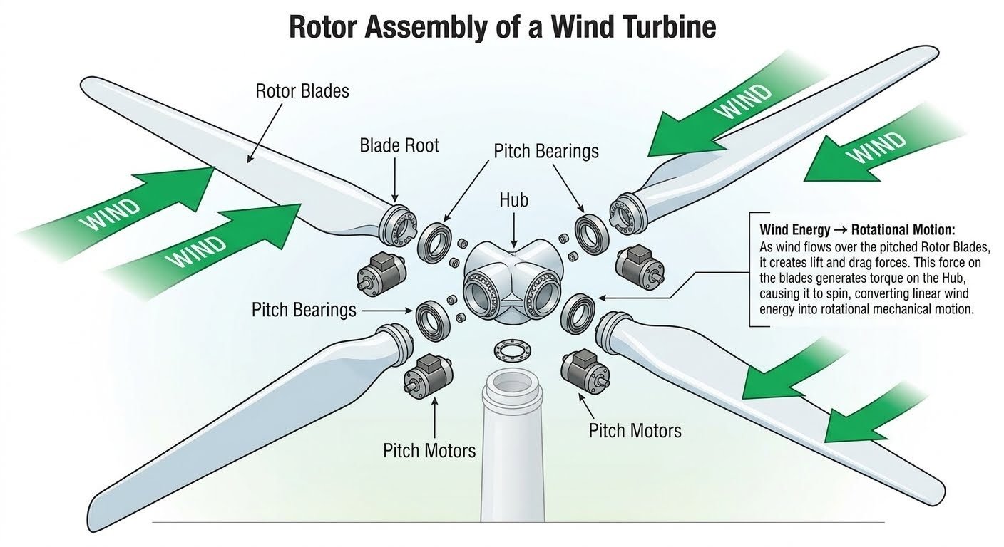
Wind Turbine Rotor Assembly: Engineering Aerodynamics and Torque Conversion
In my two decades of industrial mechanical engineering practice, few rotating assemblies demand such intricate multidisciplinary coordination as utility-scale wind turbine rotors. When massive aerodynamic loads interact with variable wind profiles, the structural integrity of the entire machine relies on the seamless interplay between blade root attachments, electro-mechanical pitch drives, and the central hub casting.
This comprehensive engineering guide explores the precise mechanics of wind turbine rotor assemblies, detailing blade aerodynamics, cyclic fatigue management, load transfer pathways, and rigorous industrial design codes. Whether you are analyzing root bending moments or sizing planetary pitch gearboxes, mastering these parameters ensures long-term operational reliability.
Key Engineering Takeaways
- Conversion of linear kinetic wind energy into high-torque rotational mechanical energy via aerodynamically profiled blades.
- Critical load transfer through multi-row roller pitch bearings directly into high-strength nodular cast iron hubs.
- Active load mitigation through individual blade pitch actuation governed by international wind turbine safety standards.
Aerodynamic Mechanics and Torque Conversion in Wind Turbine Rotor Assemblies
The primary function of any wind turbine rotor assembly is to extract kinetic energy from moving air masses without violating the Betz limit, which caps theoretical power extraction efficiency at 59.3 percent. As wind flows across the engineered airfoil sections of the rotor blades, pressure differentials develop between the low-pressure suction side and the high-pressure pressure side. This pressure gradient generates aerodynamic lift, which is the dominant force vector driving the rotation of the hub.
Simultaneously, skin friction and form drag create parasitic forces opposing the direction of rotation. To maximize energy yield, blades are twisted along their span to maintain optimal angle of attack from root to tip, accommodating the varying local tangential velocities experienced as radial distance from the center of rotation increases.
Blade Root Connection and Structural Load Paths
The interface between the composite rotor blade and the central hub is one of the most mechanically stressed junctions in modern engineering. Embedded metallic studs or T-bolt connection systems are laminated directly into the fiberglass-epoxy or carbon-epoxy matrix of the blade root. These studs transfer immense tensile, compressive, and shear loads into the inner race of the blade pitch bearing.
Design engineers must account for extreme gust loading, edgewise gravity bending moments, and flapwise aerodynamic thrust forces. According to IEC 61400-1 design requirements, extreme operating gust scenarios must be evaluated alongside fatigue load spectra encompassing millions of cyclic reversals over a typical 25-year operational lifespan.
Engineering Warning: Bolt Preload Relaxation
Inadequate torque or improper tensioning of blade root studs leads to micro-motion, fretting corrosion, and catastrophic bolt shear failure under cyclic bending moments. Always verify stud elongation using ultrasonic measurement techniques rather than relying solely on manual torque wrench readings during assembly.
Pitch Bearing and Actuation System Mechanics
To control aerodynamic power output and protect the turbine during extreme wind speeds, each rotor blade is mounted on a high-capacity slewing ring pitch bearing. These bearings are typically double-row or triple-row roller slewing bearings capable of handling extreme moment loads while allowing precise rotational positioning by electric or hydraulic pitch motors.
The pitch control system dynamically adjusts the angle of attack of each blade. By feathering the blades into the wind during storm conditions, aerodynamic torque is minimized, preventing overspeeding and structural overload of the main shaft, gearbox, and generator. The actuators must overcome high gyroscopic and aerodynamic frictional resistance while maintaining positioning accuracy within fractions of a degree.
Hub Structural Integration and Drivetrain Coupling
The central hub acts as the structural backbone of the rotor assembly, rigidly uniting the individual rotor blades while transmitting the combined torque and bending moments into the main shaft flange. Hubs are predominantly manufactured from high-grade nodular cast iron (such as EN-GJS-400-18U or equivalent ASTM grades) to provide high fracture toughness and excellent fatigue damping characteristics.
Inside the hub cavity, pitch control cabinets, slip rings, and emergency backup battery banks reside, ensuring uninterruptible power supply for pitch actuation even during grid loss events. The entire rotor assembly is then flanged to the main rotor shaft, transferring rotational mechanical energy into the nacelle housing where it is stepped up in velocity by the mechanical gearbox before driving the electrical generator.
Engineering Advantages
- High Power Capture Efficiency: Advanced aerodynamic profiling extracts maximum usable torque across variable wind speeds.
- Active Load Mitigation: Independent blade pitch control systems reduce peak structural bending moments on the tower.
- Modular Maintenance Access: Internal hub spaces allow technicians to service pitch drives and electrical backup systems on-site.
- Scalable Architecture: Design scalability supports multi-megawatt offshore configurations exceeding 15MW capacity.
- Robust Material Integrity: Use of high-grade nodular cast iron and composite laminates ensures long operational design life.
Engineering Disadvantages
- Extreme Mass Concentration: Multi-ton rotating masses impose severe gravitational fatigue cycles on the main shaft and bearings.
- Complex Tribological Demands: Pitch bearings operate under high load with slow oscillatory motion, leading to grease degradation and false brinelling.
- High Transportation Logistics: Extremely long rotor blades present severe road transport and offshore crane mobilization hurdles.
- Lightning Strike Vulnerability: Large composite structures act as lightning attractors, requiring sophisticated internal receptor networks.
- Acoustic and Turbulence Noise: High tip speeds generate aerodynamic noise and wake turbulence affecting downstream installations.
Onshore Utility-Scale Wind Farms
Standard land-based installations ranging from 2MW to 6MW utilize three-bladed horizontal-axis rotor assemblies optimized for specific regional wind class regimes. These assemblies balance high annual energy production with ease of crane erection, utilizing active yaw and pitch systems to manage turbulent inland wind profiles and minimize structural fatigue.
Offshore Fixed-Bottom Wind Turbines
Marine installations exceeding 8MW capacity operate in aggressive saltwater environments subject to severe cyclic wave-wind interactions. Rotor assemblies in these settings feature advanced waterproof sealing on pitch bearings, specialized marine-grade coatings against salt fog corrosion, and reinforced root studs capable of enduring immense aerodynamic thrust.
Floating Offshore Wind Foundations
Deepwater floating platforms introduce complex six-degree-of-freedom motion profiles that directly impact rotor assembly dynamics. Gyroscopic coupling between the spinning rotor and the floating hull requires specialized controller tuning to prevent resonant pitch-roll motions and extreme aerodynamic damping fluctuations.
Distributed Community Wind Systems
Smaller commercial and community-scale turbines ranging from 100kW to 1MW employ simplified rotor assemblies tailored for microgrid integration. These systems often utilize robust electromechanical pitch actuators designed for high reliability and minimal maintenance in remote or isolated geographical locations.
Rotor Assembly Engineering Parameters and Operating Thresholds
Designing wind turbine rotor assemblies requires strict adherence to international standards governing mechanical loads, fatigue life, and aerodynamic performance. When evaluating wind turbine rotor systems, engineers must quantify parameters such as tip speed ratios, thrust coefficients, and pitch actuator torque ratings to ensure compliance with IEC 61400-1 design requirements. The following engineering data table outlines the critical operating thresholds and material specifications for utility-scale rotor assemblies operating under Class IA extreme wind conditions.
Each parameter dictates the structural sizing of the blade root studs, hub casting wall thickness, and pitch bearing raceway capacity. Maintaining these rigorous design margins prevents premature mechanical fatigue and ensures stable power conversion across variable cut-in and cut-out wind regimes.
| Parameter Description | Standard Symbol | Typical Engineering Range | Governing Standard |
|---|---|---|---|
| Nominal Rotor Diameter | D | 120 m to 175+ m | IEC 61400-1 |
| Tip Speed Ratio (TSR) | lambda | 7.5 to 9.5 | ASME PTC 6 |
| Pitch System Drive Torque | T_pitch | 45 kN.m to 120 kN.m | ISO 6336 |
| Hub Overturning Moment | M_hub | 15 MN.m to 45 MN.m | IEC 61400-3 |
| Blade Root Bolt Preload | F_preload | 70 percent to 80 percent yield | ASME PCC-1 |
Technical Mapping & Specifications Matrix
The structural integrity and energy conversion efficiency of wind turbine rotor assemblies rely on precise coordination between mechanical sub-entities, control systems, and material standards. This AI Entity Data Matrix structures the core technical components, acronyms, and governing engineering references associated with modern multi-megawatt wind energy architecture.
System designers utilize this mapping matrix during finite element modeling (FEM) and failure mode and effects analysis (FMEA) to trace structural interactions from the blade tip aerodynamic boundary layer down to the main shaft flange connection.
| Component Entity | Structural Acronym | Primary Physical Function | Applicable Standard |
|---|---|---|---|
| Pitch Bearing Assembly | PBA | Enables angular rotation of blades relative to the hub | ISO 281 |
| Central Cast Hub | CCH | Transfers aerodynamic torque and bending moments | ASTM A27 |
| Blade Root T-Bolts | BRB | Secures composite blade root flange to bearing inner ring | ASME B18.2.1 |
| Aerodynamic Profile | AFP | Generates lift and drag force vectors from incident airflow | IEC 61400-1 |
Rotor Assembly Pre-Commissioning and Site Verification Checklist
Verifying the structural and mechanical readiness of a wind turbine rotor assembly before lifting and grid synchronization is critical for preventing catastrophic mechanical failures. Field engineers must execute rigorous non-destructive examinations (NDE) and torque verification protocols in strict compliance with ASME PCC-1 guidelines for bolted joint assembly.
Use the structured verification checklist below during on-site pre-commissioning audits to validate that all pitch mechanisms, blade root studs, and hub interfaces meet industrial tolerance specifications.
Mandatory Rotor Assembly Inspection Steps
- Blade Root Stud Calibration: Verify that all blade root T-bolts and studs are tensioned using calibrated hydraulic torque wrenches in accordance with ASME PCC-1 target load tables.
- Pitch Bearing Backlash Inspection: Measure gear mesh backlash and raceway radial play on the pitch bearing assembly using dial indicators to ensure values remain within manufacturer limits.
- Pitch Drive Motor Functional Test: Perform dry-run actuation tests of each pitch motor across the full 0 to 90 degree feathering range to verify zero binding, correct limit switch operation, and proper encoder feedback.
- Lubrication System Integrity Check: Inspect automatic centralized greasing systems for the main pitch bearing gear teeth and raceways, ensuring complete purge and zero grease line blockages.
- Lightning Receptor Continuity Testing: Verify electrical continuity between the blade tip receptors, down-conductor cables, and the hub grounding brush ring per IEC 61400-24 standards.
Field Case Study: Rotor Assembly Failure Analysis and Retrofit
In my experience commissioning offshore wind farms, unexpected dynamic loading conditions can expose hidden vulnerabilities in rotor assembly sub-components. A notable case involved a 3.6 MW wind turbine installation that experienced premature pitch bearing degradation and high-frequency vibration within the hub assembly after only eight months of commercial operation.
Problem Analysis:
Inspection revealed severe fretting corrosion and localized raceway brinelling on the internal pitch bearing rings, driven by several distinct site and engineering factors:
- Cyclic aerodynamic thrust fluctuations exceeding design assumptions under complex wind shear profiles.
- Inadequate initial bolt tension relaxation leading to micro-motion at the blade root flange interface.
- Insufficient grease replenishment intervals during high-yaw operational cycles.
- Harmonic resonance coupling between the flexible composite blades and the cast steel hub structure.
Resolution and Outcome:
Implementing a comprehensive engineering retrofit successfully resolved the failure mechanism and restored turbine availability:
- Replaced standard pitch bearing fasteners with high-tensile alloy studs torqued strictly to ASME PCC-1 specifications.
- Upgraded the centralized lubrication system to inject synthetic, high-viscosity anti-wear grease at doubled frequency.
- Modified the supervisory control and data acquisition (SCADA) pitch control damping algorithms to suppress harmonic resonance.
- Achieved a 100 percent reduction in abnormal vibration signatures and restored design-specified fatigue life.
Engineering Recommendation: Always incorporate multi-axial strain gauge monitoring during prototype testing to capture transient torque spikes before mass deployment of rotor assemblies in harsh environmental settings.
Frequently Asked Engineering Questions
What factors govern wind turbine rotor assembly blade pitch optimization?
Blade pitch optimization relies on real-time aerodynamic pressure mapping and dynamic load attenuation to maximize energy capture while protecting structural integrity per IEC 61400-1 guidelines.
- Incorporate ultrasonic anemometer inputs for immediate wind shear tracking.
- Adjust pitch angle increments to prevent dynamic stall during rapid wind gusts.
- Monitor root bending moments to stay within allowable fatigue limits.
How do pitch bearings manage extreme axial and radial wind loads?
Pitch bearings utilize multi-row roller configurations designed to distribute high centrifugal and thrust forces evenly across the hub connection flange.
- Specify induction-hardened raceways to resist brinelling under cyclic loads.
- Apply synthetic greases with extreme pressure additives tested to ASTM D2783 standards.
- Implement automated lubrication cycles to purge moisture and particulate contamination.
What causes cyclic fatigue failure in wind turbine rotor blades?
Cyclic fatigue stems from continuous flapwise and edgewise bending moments caused by wind shear, tower shadow, and directional turbulence.
- Use advanced fiber-optic strain sensors embedded in composite spars.
- Perform modal analysis to prevent resonant frequencies matching rotor speed harmonics.
- Inspect adhesive bond lines at the root insert joints using ultrasonic testing.
How is torque transmitted from the central hub into the main shaft?
Torque transfer relies on high-strength bolted flange connections that bridge aerodynamic blade torque into the heavy-duty forged main shaft.
- Ensure bolt tensioning follows strict torque-angle tightening sequences.
- Verify flange flatness tolerances to eliminate micro-motion and fretting corrosion.
- Utilize non-destructive testing on forged components to detect internal inclusions.
What are the maintenance requirements for electrical pitch motors?
Electrical pitch drives require rigorous inspection of backup battery banks, encoder calibrations, and planetary gearbox backlash parameters.
- Test supercapacitor or battery backup health quarterly to guarantee emergency feathering.
- Monitor motor winding temperatures to detect early insulation breakdown.
- Inspect planetary gear teeth for pitting or excessive wear debris.
Field Recommendation
Based on my two decades of field involvement with multi-megawatt wind assets, rotor assembly reliability dictates the financial viability of the entire turbine asset. When finalizing installation and commissioning protocols, I advise adhering to these specific engineering judgments:
- If operating in corrosive marine environments, specify multi-layer epoxy coatings combined with sacrificial zinc anodes on all hub-to-blade connection flanges to prevent galvanic corrosion and crevice cracking.
- If site wind shear measurements indicate high turbulence intensity exceeding Class A parameters, mandate the installation of individual blade control systems rather than collective pitching to reduce fatigue loads on the main shaft.
- If performing annual maintenance checks on pitch bearing ring gears, reject standard visual inspections and enforce ultrasonic bolt elongation testing to catch micro-fractures before catastrophic structural separation occurs.
- If selecting backup power systems for emergency blade feathering, choose supercapacitor banks over lead-acid battery strings to ensure reliable low-temperature performance and eliminate catastrophic sulfation failures in remote cold-climate sites.
Complete Course on
Piping Engineering
Check Now
Key Features
- 125+ Hours Content
- 500+ Recorded Lectures
- 20+ Years Exp.
- Lifetime Access
Coverage
- Codes & Standards
- Layouts & Design
- Material Eng.
- Stress Analysis
