Mastering Wind Turbine Foundation Construction and Curing Protocols
In my two decades managing industrial infrastructure and heavy civil construction, I have observed that the success of any multi-megawatt wind turbine installation depends entirely on the precision of its sub-surface concrete mass. Once the anchor cage and rebar assembly are verified in position, the wind turbine foundation proceeds through the concrete pour and curing sequence – placing reinforced concrete around the embedded anchor cage and rebar network, then allowing it to cure to design strength before backfilling and permitting any load application from the tower structure above.
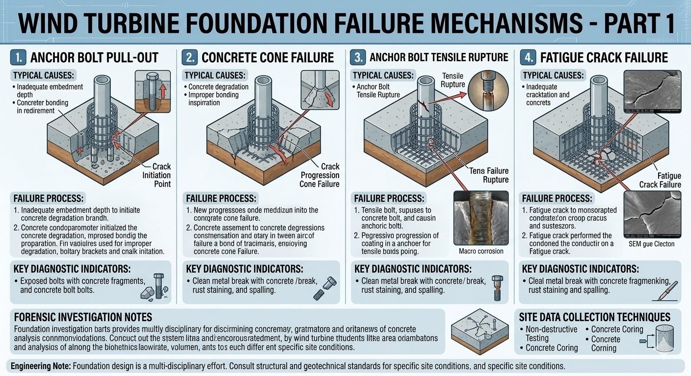
Maintaining exacting tolerances during this structural phase prevents catastrophic fatigue failures under severe cyclic wind loading. Every millimeter of angular deviation at the anchor flange magnifies into critical bending moments hundreds of feet up at the nacelle level.
Key Engineering Takeaways
- Anchor cage spatial alignment must be verified via total station before continuous concrete placement commences.
- Thermal control plans are mandatory for mass concrete pours exceeding 1.5 meters thickness to prevent core cracking.
- Curing monitoring via maturity meters ensures unyielding compressive strength compliance prior to tower erection.
Wind Turbine Foundation Engineering and Structural Integrity
Constructing a modern gravity-base wind turbine foundation requires synchronizing geotechnical engineering, high-performance concrete mix design, and hyper-accurate steel assembly. As rotor diameters exceed 150 meters, overturning moments transferred through the tower base escalate exponentially. This demands absolute rigidity from the embedded anchor cage and the surrounding monolithic concrete block.
The construction sequence begins after the excavation and blinding concrete layer are approved. Surveyors establish primary coordinate grids while steel fixers erect the heavy reinforcement cage. Concurrently, the post-tensioned or cast-in anchor ring is suspended and braced using heavy structural steel framing to prevent distortion during subsequent concrete placement.
Core Engineering Parameters for Mass Pours
- Maximum Core Temperature: Must not exceed 70 degrees Celsius to prevent delayed ettringite formation (DEF).
- Temperature Differential: Maximum allowable delta between core and surface is 20 degrees Celsius to avoid thermal cracking.
- Concrete Slump Range: Maintained between 180mm and 220mm using polycarboxylate-based superplasticizers for smooth flow through congested rebar.
- Vibration Protocol: Systematic needle immersion at 500mm intervals with 15-second dwell times to eliminate honeycombing around anchor sleeves.
Anchor Cage Alignment and Tolerances
The anchor cage serves as the mechanical interface between the reinforced concrete mat and the steel tubular tower flange. Even minor angular misalignments exceeding 0.05 degrees will induce severe localized stress concentrations upon bolt torquing.
Field teams must utilize laser trackers and optical levels to verify bolt circle diameters, elevation planes, and plumbness continuously. Templates welded to the upper and lower anchor flanges lock the threaded rods in spatial harmony, resisting the buoyant forces exerted by wet concrete during aggressive pumping operations.
Critical Engineering Warning: Thermal Stress Management
Mass concrete elements thicker than two meters generate immense heat of hydration. Without internal cooling pipes or fly ash replacement exceeding 30 percent, core temperatures will spike, leading to micro-cracking that compromises shear transfer capacity under cyclic wind loads. Monitor internal thermocouple arrays continuously for the first 14 days post-pour.
Continuous Concrete Pouring Methodology
Cold joints within the structural core of a wind turbine foundation are strictly prohibited due to their susceptibility to moisture infiltration and fatigue failure. A continuous pour strategy utilizing multiple boom pumps is mandatory for high-capacity foundations containing upwards of 500 cubic meters of concrete.
Logistical planning must account for batch plant proximity, traffic contingencies, and backup generator availability. The placement rate must maintain a fluid front across the entire formwork area, allowing fresh layers to knit seamlessly into preceding lifts before initial set occurs.
Curing Regimes and Strength Development
Achieving the specified 28-day compressive strength (typically 35 to 45 MPa) requires strict adherence to moisture retention and temperature management protocols outlined in ACI 308. Premature drying halts cement hydration, leaving surface layers porous and vulnerable to carbonation.
Water curing via sprinkler systems or saturated burlap blankets must continue for a minimum of seven consecutive days. Maturity meters embedded at critical depths calculate real-time strength development based on time-temperature history, granting site managers empirical justification for early backfilling and crane mobilization.
Advantages
- High structural mass effectively dampens dynamic overturning moments from high-velocity turbine rotors.
- Monolithic gravity design requires minimal maintenance over a standard 25-year operational lifecycle.
- Embedded anchor cages provide exceptional tensile and shear load transfer into the earth substrate.
- Adaptable to diverse geotechnical profiles through integration with deep driven or bored pile caps.
- Locally sourced concrete aggregates reduce transportation emissions and material acquisition costs.
Disadvantages
- Massive cement volumes generate high hydration heat, necessitating complex thermal control measures.
- Continuous batching logistics require flawless execution to eliminate catastrophic cold joint risks.
- Rigid dimensional tolerances leave zero margin for error during anchor cage positioning.
- Substantial excavation and backfill earthwork requirements extend overall project mobilization timelines.
- Vulnerable to chemical degradation if aggressive groundwater sulfate levels exceed mix design tolerances.
Onshore Ridge Installations
Mountainous terrain installations demand specialized earthmoving and stepped gravity foundations to accommodate steep slopes. Precision leveling pads and rock anchors lock the mass concrete block into stable bedrock formations, preventing sliding under severe lateral wind shear forces.
Coastal Plain Wind Farms
Low-lying coastal sites characterized by high water tables require deep pile-supported foundation caps combined with sulfate-resistant cement mixes. Dewatering systems must operate continuously throughout the excavation, rebar tying, and concrete pouring sequence to preserve structural integrity.
Repowering Brownfield Sites
Upgrading older wind farms often involves demolishing legacy foundations or retrofitting existing gravity bases with post-installed anchor extensions. Engineers utilize non-destructive testing and core sampling to verify the residual capacity of legacy mass concrete before mounting higher-capacity turbines.
Cold Climate High-Latitude Projects
Sub-arctic installations require heated formwork systems, insulated curing blankets, and anti-freeze admixtures to ensure proper cement hydration during freezing ambient temperatures. Thermal monitoring prevents early-age freezing damage that would permanently destroy concrete tensile strength.
Concrete Mix and Curing Parameters for Wind Turbine Foundations
Successful heavy civil construction for renewable energy infrastructure requires strict adherence to material property thresholds during both the batching and hydration phases. The data compiled below establishes the operational baseline for high-strength reinforced concrete utilized in onshore utility-scale tower pedestals, incorporating provisions from ASTM International and American Concrete Institute guidelines.
Engineers must monitor core hydration temperatures continuously to prevent thermal cracking induced by the exothermic reaction of massive cementitious volumes. The reference table outlines critical targets for slump retention, compressive strength gain, and water-cement ratios.
| Parameter Specification | Standard Target Value | Governing Code / Standard | Verification Method |
|---|---|---|---|
| Maximum Water-Cement Ratio | 0.38 to 0.42 max | ACI 318 / ASTM C94 | Batch Plant Ticket Audit |
| Target Slump at Placement | 150 mm +/- 25 mm | ASTM C143 | Abrams Cone Slump Test |
| Minimum Compressive Strength (f’c) | 35 MPa to 45 MPa at 28 days | ASTM C39 | Cylindrical Break Testing |
| Core Temperature Differential | Maximum 20 deg C delta | ACI 207.2R | Embedded Thermocouple Array |
| Minimum Wet Curing Duration | 7 Continuous Days | ACI 308.1 | Visual & Moisture Logging |
Note: All mix designs must be pre-qualified through trial batching under site-specific ambient thermal conditions prior to mass placement operations.
Technical Mapping & Specifications Matrix
To ensure seamless integration between structural geotechnical design and mechanical tower loading, every material entity within the reinforced concrete assembly must be cataloged. The matrix below links physical structural components with their governing engineering standards and quality assurance protocols.
Navigating these interrelated entities prevents structural degradation and guarantees long-term fatigue resistance against dynamic wind shear moments.
| Structural Entity | Material Grade | Primary Code Standard | Inspection Frequency |
|---|---|---|---|
| Anchor Cage Assembly | ASTM A615 Gr. 75 / DIN 1.7225 | ASME BPVC / ISO 19901 | 100% Non-Destructive Testing |
| Rebar Reinforcement Network | ASTM A706 Grade 60 (Low Alloy) | ACI 318 Chapter 20 | Prior to Every Concrete Pour |
| Foundation Mass Concrete | Portland Cement Type II/V Blend | ASTM C150 | Continuous Batch Sampling |
| Grout Interface Layer | Non-Shrink Epoxy / Cementitious | ASTM C1107 | Post-Curing Core Extraction |
| Geotechnical Subgrade | Compacted Aggregate / Mud Slab | ASTM D1557 | Proctor Density Testing |
Entity mapping is validated against finite element structural models to confirm compliance with site wind velocity classifications.
Site Verification Checklist: Wind Turbine Foundation Execution
Site verification is the final line of defense before executing mass concrete placement for a wind turbine foundation. Quality control engineers must systematically verify anchor cage plumbness, rebar clearance, and formwork stability in strict accordance with ACI 318 standards. Skipping any verification item invites catastrophic foundation settlement under cyclic overturning moments.
The following structured checklist must be executed and signed off by both the civil contractor and the independent third-party geotechnical inspector prior to dispatching the first concrete mixer truck to the pad.
Mandatory Pre-Pour Site Verification Steps
- Anchor Bolt Alignment Check: Verify template ring elevations and bolt center-to-center tolerances within plus or minus 1.5 mm using calibrated total stations.
- Rebar Clear Cover Inspection: Confirm bottom and side reinforcement mats maintain a minimum of 75 mm clear cover from earth or mud slab surfaces per ACI specifications.
- Formwork Rigidity Audit: Inspect perimeter form bracing, tie rods, and kickers to ensure zero displacement during high-pressure pump placement.
- Subgrade Cleansing Validation: Ensure excavation pit is completely free of standing water, loose debris, and collapsed sidewall soil prior to placement.
- Thermocouple Placement: Secure thermal sensors at core and surface locations to monitor mass concrete temperature gradients during hydration.
- Batch Plant Logistics Review: Confirm continuous delivery scheduling, testing technician availability, and backup power generators for vibrators.
Upon complete execution of this checklist, the quality manager shall issue a formal “Permit to Pour” certificate. Any deviations noted during inspection must be remediated and re-verified before batching operations commence.
Field Case Study: Real-World Application
Examining actual site anomalies provides invaluable insight into the rigorous demands of utility-scale wind turbine foundation construction. The following case study details a challenging mass concrete pour on a high-wind ridgeline site and the engineering measures implemented to preserve structural integrity.
Problem Encountered:
During a massive 450-cubic-meter continuous concrete pour for a 3.6 MW wind turbine pedestal, sudden ambient temperature spikes combined with high winds caused rapid surface moisture evaporation and premature plastic shrinkage cracking around the anchor cage assembly.
- Ambient temperatures exceeded 38 degrees Celsius during midday placement.
- Evaporation rates surpassed the critical 1.0 kg/m² /hr threshold defined in ACI 305R.
- Initial surface inspection revealed hairline micro-cracks propagating outward from anchor bolt sleeves.
- Wind gusts up to 45 km/h accelerated bleeding water loss across the exposed upper footing surface.
Resolution and Outcome:
Immediate engineering intervention halted standard finishing operations and deployed emergency mitigation protocols to safeguard the structural design strength.
- Deployed fogging sprays and erected temporary wind-break baffling around the perimeter formwork.
- Applied aliphatic alcohol evaporation retarder immediately after screeding to lock in internal moisture.
- Initiated continuous wet burlap curing and insulated blankets 4 hours ahead of schedule.
- Core sample testing at 28 days confirmed compressive strengths exceeded design specifications (f’c = 42.5 MPa achieved).
This field event emphasizes that proactive environmental monitoring and rapid contingency readiness are mandatory when executing heavy civil wind energy foundations under adverse meteorological conditions.
Frequently Asked Engineering Questions
What are the key tolerances for anchor cage positioning during a wind turbine foundation pour?
- Top bolt elevation must be maintained within plus or minus 3 mm of design grade.
- Bolt circle diameter verification requires laser measurement across opposing studs.
- Radial orientation must align with the primary prevailing wind directional vector.
How is thermal cracking managed during massive mass-concrete pours for gravity bases?
- Substitute up to 50 percent of Portland cement with fly ash or slag to lower peak hydration heat.
- Pre-cool concrete mixes using liquid nitrogen or chilled batch water during hot weather.
- Deploy embedded thermocouple arrays to monitor real-time temperature differentials continuously.
What are the minimum curing duration requirements before backfilling a turbine foundation?
- Concrete must achieve at least 70 percent of its specified 28-day compressive strength.
- Maturity meters and field-cured cylinders validate in-situ strength development accurately.
- Backfill operations must proceed in uniform, compacted lifts symmetrically around the structure.
Why is continuous concrete placement mandatory for wind turbine gravity foundations?
- Plan redundant batch plant capacity to avoid supply chain interruptions during the pour.
- Establish strict delivery queue schedules with transit mixers spaced at precise intervals.
- Ensure standby pumping units are operational on-site to handle sudden equipment breakdowns.
How do site geotechnical conditions dictate the choice of foundation reinforcement?
- High-plasticity soils require expansive reinforcement mats to resist differential settlement.
- Aggressive groundwater chemistry mandates epoxy-coated or stainless steel rebar networks.
- Piled foundation caps need robust shear reinforcement around deep foundation pile heads.
Field Recommendation
Drawing from decades of heavy civil and structural engineering execution on industrial wind energy sites, I advise project teams to treat foundation execution as an unforgiving precision operation. Here are my definitive professional judgment calls for field implementation:
- If site ambient temperatures exceed thirty degrees Celsius during scheduled mass pours, mandate the use of liquid nitrogen cooling and retarder admixtures immediately to prevent flash setting and micro-cracking across the anchor ring assembly.
- If anchor cage survey checks reveal a vertical plumb deviation exceeding two millimeters, halt all placement operations instantly and re-tension the restraining jigs before concrete truck dispatch resumes from the batch plant.
- If geotechnical reports indicate high sulfate concentrations in groundwater, upgrade reinforcement specifications to epoxy-coated rebar and specify Sulfate-Resisting Portland Cement to guarantee the fifty-year design life required by ASTM standards.
- If continuous concrete supply is threatened by regional traffic bottlenecks, require contractors to establish dual-plant batching agreements with dedicated haul routes to eliminate cold joints in the monolithic base.
Complete Course on
Piping Engineering
Check Now
Key Features
- 125+ Hours Content
- 500+ Recorded Lectures
- 20+ Years Exp.
- Lifetime Access
Coverage
- Codes & Standards
- Layouts & Design
- Material Eng.
- Stress Analysis
