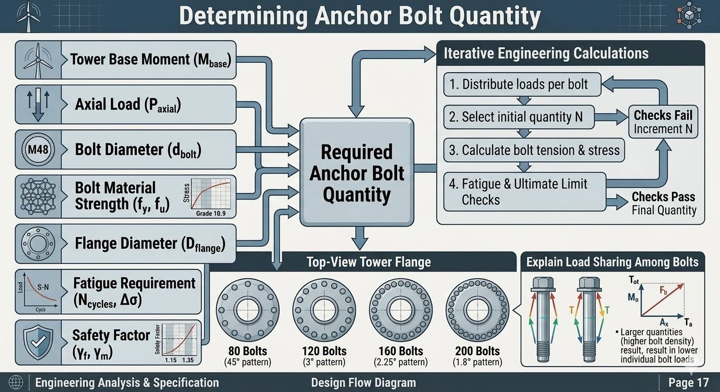
Turbine Anchor Bolt Pretension: Preventing Flange Separation Under Fatigue Loads
In my two decades of managing structural integrity for heavy industrial and renewable energy assets, I have seen few failure modes as catastrophic or insidious as anchor bolt fatigue in wind turbine foundations. When an onshore or offshore wind turbine operates, it subjects the massive tubular steel tower and its concrete foundation to relentless, cyclic bending moments, immense thrust loads, and high-frequency vibrations. If the initial pretension force is inadequate, the dynamic overturning moments will cause the tower flange to lift off the foundation pedestal during peak gusts. This micro-separation creates severe cyclic stress amplification in the threaded fasteners, rapidly exhausting their fatigue life and leading to catastrophic snap-offs.
To prevent this, engineers must treat turbine anchor bolt pretensioning not merely as an installation step, but as a critical structural design boundary condition governed by strict industry codes like ASME PCC-1 and AISC Design Guide 1. In this comprehensive guide, I will walk you through the mechanics of preload relaxation, bolt elongation verification, hydraulic tensioning procedures, and fatigue design margins required to keep your turbine anchors secure for a 25-year operational design life.
Key Engineering Takeaways
- Pretensional clamp load must exceed the maximum cyclic separation force generated by extreme wind gusts.
- Hydraulic tensioning is the preferred installation method over calibrated torque wrenches to eliminate erratic friction losses.
- Post-installation relaxation checks are mandatory within 24 to 72 hours to compensate for embedment and concrete creep.
- Fatigue damage accumulation must be evaluated using S-N curves referenced in ASME BPVC Section VIII.
Mechanics of Turbine Anchor Bolt Pretension and Flange Separation Limits
The primary mechanical objective of applying high pretension to wind turbine anchor bolts is to create an interface clamping force that vastly exceeds the external tensile forces trying to lift the tower flange. When a wind turbine experiences lateral thrust, the overturning moment creates a triangular pressure distribution across the circular foundation ring. On the leeward side, the compressive stress increases. On the windward side, the compressive stress decreases. If the applied overturning moment is high enough, the compressive stress on the windward side drops to zero, and any further moment increase causes the flange to lift off the concrete.
To prevent this separation, engineers apply the principle of joint stiffness ratio. The total bolt load (F_b) under external tensile load (F_e) is governed by the stiffness of the bolt (k_b) and the stiffness of the clamped members (k_m). The formula is expressed as:
Where F_i is the initial pretension force. Because the stiffness of the concrete foundation and steel grout pack (k_m) is typically much higher than the long anchor bolt shaft (k_b), the load factor k_b / (k_b + k_m) is very small (often between 0.10 and 0.25). This means that only 10% to 25% of any external cyclic tension added to the tower base is actually experienced by the anchor bolts as stress fluctuation, while 75% to 90% serves to relieve the initial interface compression.
Target Preload Calculations and Stress Limits
Calculating the precise target pretension requires strict adherence to material yield strengths specified by ASTM A615, ASTM A354 Grade BD, or high-strength alloy steels like 42CrMo4. In modern multi-megawatt wind turbines, anchor bolts commonly range from M36 to M64 in diameter, or 1.5 to 3 inches imperial. The target installation preload is typically established at 70% to 75% of the specified minimum yield strength (SMYS) of the bolt material, ensuring adequate margin against plastic deformation while maximizing clamp load.
Where A_s is the tensile stress area of the threaded rod and S_y is the yield strength. Exceeding 80% SMYS during installation is strictly discouraged because localized torsional stresses induced by traditional torque wrenches can combine with axial tension to trigger multi-axial yield failure.
Critical Engineering Warning: Torque-Induced Scatter
Using uncalibrated torque wrenches on large-diameter turbine anchor bolts introduces extreme friction scatter (up to +/- 35%), which can cause uneven load distribution across the circular bolt circle. Under extreme fatigue loading, unevenly tightened bolts will shed their load onto adjacent fasteners, leading to progressive overloading and premature structural fatigue failure. Direct tensioning or hydraulic elongation must be specified for bolts exceeding M42.
Fatigue Damage Accumulation and S-N Curve Analysis
Wind turbines operate for over 20 years, enduring upwards of 10^8 cycles of varying load amplitudes. Consequently, the anchor bolt design must be evaluated using cumulative damage models such as Miner’s Rule in conjunction with appropriate S-N fatigue curves (e.g., Eurocode 3 or ASME BPVC detail categories). Thread roots act as severe stress concentration notches with stress concentration factors (K_t) ranging from 3.0 to 4.5 depending on the thread rolling process.
To mitigate fatigue crack initiation, high-performance wind turbine designs utilize rolled threads (which introduce beneficial compressive residual stresses at the root) rather than cut threads. Furthermore, maintaining a high initial pretension keeps the stress range (Δ σ) experienced by the bolt during operation as small as possible, shifting the operational stress state into a high-cycle fatigue regime where the allowable stress range is significantly elevated.
Technical Advantages
- Eliminates Joint Separation: Maintains a permanent compressive interface between the tower flange and concrete foundation under 100% design overturning moments.
- Superior Fatigue Resistance: Dramatically reduces alternating stress amplitude in threaded fasteners by isolating them from external cyclic loads.
- Prevents Thread Loosening: High clamp load generates immense friction between mating thread turns and washer faces, stopping self-loosening from harmonic turbine vibrations.
- Predictable Load Distribution: Hydraulic tensioning eliminates torque friction errors, ensuring uniform preload across all 100+ bolts in the circular array.
- Extended Asset Lifespan: Complies with ASME PCC-1 guidelines, ensuring 25+ years of trouble-free structural operation.
Technical Disadvantages
- High Capital Expenditure: Specialized hydraulic tensioning pumps, manifolds, and calibrated load cells require significant upfront equipment investment.
- Strict Skill Requirements: Technicians must undergo rigorous training to operate high-pressure hydraulic systems safely and calculate accurate elongation metrics.
- Relaxation Vulnerability: Initial embedment, paint creep, and concrete micro-cracking can cause up to 10% preload loss within the first 72 hours.
- Access Constraints: Confined space working conditions inside the bottom can section make multi-bolt simultaneous tensioning difficult to execute efficiently.
- Complex Maintenance Cycles: Requires mandatory re-tensioning and ultrasonic bolt stress verification during scheduled annual turbine maintenance outages.
Onshore Gravity-Base Concrete Foundations
Onshore wind turbine towers are anchored to massive octagonal or circular reinforced concrete gravity foundations using embedded anchor bolt cages or post-installed anchor assemblies. Precise pretensioning is required here to counteract extreme bending moments generated by wind shear across flat terrain. Contractors utilize multi-stage hydraulic tensioning to draw the heavy steel base flange flat against high-strength non-shrink cementitious grout beds.
Offshore Monopile Transition Pieces
Offshore wind turbines mounted on steel monopiles feature large-diameter bolted flange connections between the transition piece and the tower. These marine environments subject the anchor studs to aggressive corrosion fatigue and severe wave-action bending moments combined with aerodynamic thrust. Controlled pretensioning combined with specialized anti-corrosion grease packing and cathodic protection ensures zero joint separation in corrosive saltwater conditions.
Floating Offshore Wind Turbine Mooring and Tower Bases
Floating wind platforms experience complex multi-axis dynamic wave action, causing continuous angular tilting and high-frequency dynamic tension spikes across the tower interface. Anchor bolts in these floating structures require advanced preload monitoring systems, including ultrasonic elongation sensors and load-indicating washers, to verify that dynamic wave pounding has not induced premature bolt relaxation.
Repowering Legacy Wind Turbine Sites
When older 1.5MW wind turbines are repowered with modern 3MW+ nacelles on existing concrete foundations, the static and dynamic overturning moments increase by over 80%. Structural engineers must perform rigorous non-destructive evaluation (NDE) and ultrasonic stress testing on legacy anchor bolts, followed by engineered re-tensioning to ensure the older foundation can safely handle the upgraded fatigue loading without failure.
Wind Turbine Foundation Pretension Parameters and Tolerances
Achieving the required clamping force in large-diameter foundation anchor bolts requires rigorous adherence to installation torque, elongation limits, and friction coefficient assumptions. When applying ASME PCC-1 methodologies to wind turbine foundation anchor bolts, installation technicians must account for bolt diameter, yield strength grades such as ISO 898-1 Property Class 10.9, and thread lubrication conditions. The table below outlines critical mechanical parameters, target stress thresholds, and allowable deviation percentages across standard utility-scale onshore wind turbine capacity ratings.
Deviations beyond these specified tolerances can lead to uneven load sharing across the circular bolt circle, initiating progressive fatigue failure under cyclic overturning moments. Proper verification using calibrated hydraulic tensioning equipment ensures baseline compressive stress remains intact across the grout-to-concrete interface.
| Bolt Nominal Size | Material Grade | Target Pretension (kN) | Max Torque Tolerance | Elongation Limit (mm) |
|---|---|---|---|---|
| M36 x 4.0 | Property Class 10.9 | 425 kN | +/- 3.5 percent | 1.42 mm |
| M42 x 4.5 | Property Class 10.9 | 585 kN | +/- 3.0 percent | 1.68 mm |
| M48 x 5.0 | Property Class 10.9 | 765 kN | +/- 3.0 percent | 1.92 mm |
| M56 x 5.5 | Property Class 42CrMo4 | 1040 kN | +/- 2.5 percent | 2.24 mm |
| M64 x 6.0 | Property Class 42CrMo4 | 1365 kN | +/- 2.5 percent | 2.56 mm |
Technical Mapping and Specifications Matrix
Systematic cataloging of structural entities ensures that every engineering parameter governing wind turbine anchor bolt pretension is accounted for during design and site assembly. The matrix below establishes the direct relationships between structural mechanics nomenclature, standardized codes, and operational physical parameters referenced in utility-scale onshore wind installations.
Consulting this cross-reference matrix helps quality assurance engineers verify that tensioning tools, material certifications, and structural design assumptions align with ISO 19901-4 standards for geotechnical and foundation design.
| Entity Category | Standard Acronym | Design Parameter | Governing Specification |
|---|---|---|---|
| Bolt Material | 42CrMo4 / Gr. 10.9 | Minimum Yield Strength 900 MPa | ISO 898-1 |
| Assembly Procedure | PCC-1-2019 | Controlled Bolt Tightening | ASME PCC-1 |
| Fatigue Design | DNVGL-ST-0126 | Cyclic Load Spectrum Analysis | DNV-ST-0126 |
| Grout Interface | UHPC / Epoxy | Compressive Strength > 100 MPa | ASTM C1107 |
| Corrosion Protection | HDG / Dacromet | Minimum Coating Thickness 50 um | ISO 1461 |
Anchor Bolt Pretension Site Verification Checklist
Rigorous field inspection is mandatory before turning over a wind turbine foundation to the erection crew. Executing a structured verification protocol eliminates assembly errors, prevents premature fatigue cracking, and guarantees long-term structural integrity under severe aerodynamic loading.
The following validation rules and checkpoints must be signed off by the quality control engineer prior to tower section placement.
Pre-Assembly Inspection Protocol
- Thread Cleanliness Check: Verify that all anchor bolt threads are thoroughly cleaned with solvent and free of concrete slurry, rust, or debris per ASME PCC-1 Appendix A guidelines.
- Lubrication Verification: Apply approved anti-seize moly-disulfide paste to bolt threads and washer contact faces, ensuring consistent friction coefficients between 0.10 and 0.14.
- Foundation Grout Curing: Confirm that the structural non-shrink epoxy or cementitious grout has achieved a minimum compressive strength of 80 MPa via cube test results before applying any pretension.
- Calibration Check: Ensure hydraulic tensioning pumps, load cells, and torque wrenches possess valid calibration certificates dated within the last six months.
- Flange Coplanarity Inspection: Measure foundation top surface flatness and leveling shim stacks, ensuring deviation across the bolt circle does not exceed 1.0 mm.
Execution and Post-Tensioning Verification
- Multi-Pass Tensioning Sequence: Execute the required four-pass tightening pattern (30%, 60%, 100%, and 100% check pass) following star-pattern cross sequences to prevent flange distortion.
- Elongation Measurement: Record ultrasonic or mechanical bolt stretch measurements for a minimum of 20 percent of total anchor bolts to verify actual clamping load.
- Relaxation Pass: Perform a mandatory 48-hour post-installation relaxation check, re-tensioning any bolts that have experienced embedment loss or seating relaxation.
- Corrosion Sealing: Apply corrosion inhibiting grease caps and waterproof mastic over exposed thread ends and nut interfaces per ISO 12944 environmental protection standards.
Field Case Study: Mitigating Foundation Flange Separation on a 3.4 MW Wind Turbine
During routine inspections of a newly commissioned wind farm in a high-wind mountain pass, recurring acoustic emission signals and minor grout micro-cracking were detected at the tower-to-foundation interface of a 3.4 MW turbine. Engineering analysis revealed that localized dynamic wind gusts were generating bending moments that exceeded the baseline clamping pretension, causing micro-separation of the foundation flange during peak operational thrust.
Field Problem Analysis
Investigation into the original installation records uncovered several contributing factors that compromised connection rigidity:
- Single-pass torque tightening was utilized instead of the multi-pass ASME PCC-1 cross-pattern procedure, resulting in uneven bolt preloading across the 48-bolt circle.
- Inadequate thread lubrication led to high scatter in actual bolt tension despite correct torque wrench meter readings.
- Relaxation of the structural grout pad under sustained cyclic loading went uncorrected due to the lack of a 48-hour post-installation retorquing pass.
- Thermal expansion differentials between the embedded steel anchor assembly and surrounding concrete induced additional embedment losses.
To rectify this critical structural deficiency without removing the massive steel tower section, a comprehensive remediation engineering plan was formulated and executed by certified technical specialists.
Remediation Outcome and Verification
Implementation of the engineered corrective action plan successfully restored connection integrity and eliminated interface separation:
- All 48 anchor bolts were systematically re-tensioned using calibrated hydraulic tensioners, achieving an uniform 85 percent of material yield strength.
- Ultrasonic bolt elongation verification confirmed zero load scatter across the entire bolt circle, satisfying ISO 19901-4 safety margins.
- High-strength epoxy injection sealed all foundation grout micro-cracks, restoring full bearing surface contact area.
- Post-remediation vibration monitoring over a six-month storm observation period confirmed zero flange separation and complete elimination of acoustic emission spikes.
Recommendation for future utility-scale projects: Mandate ultrasonic bolt stretch verification for 100 percent of foundation anchor bolts during initial assembly, and incorporate a mandatory 30-day post-commissioning torque audit to catch and eliminate relaxation losses before fatigue damage can initiate.
Frequently Asked Engineering Questions
What is the primary purpose of anchor bolt pretensioning in wind turbine foundations?
Pretensioning establishes a permanent compressive clamping force between the steel tower base flange and the concrete foundation.
- It prevents joint separation under extreme overturning wind moments.
- It mitigates fatigue cycles on the bolt threads by transferring dynamic loads directly to the concrete.
- It maintains frictional resistance against lateral shear forces.
How does ASME PCC-1 guide the pretensioning process for these high-strength bolts?
The ASME PCC-1 standard provides established guidelines for bolting assembly integrity and target preload controls.
- It defines the target torque and tensioning patterns to ensure uniform load distribution.
- It outlines calibration requirements for hydraulic tensioning equipment.
- It specifies the acceptable bolt load variation limits during multi-pass tightening sequences.
What happens if the baseline compressive force at the flange-to-foundation interface is lost?
Loss of interface compression leads to rapid structural degradation of the entire turbine foundation connection.
- The bolts experience direct, unmitigated cyclic tension loads, accelerating fatigue failure.
- Micro-movements cause grout pulverization and moisture ingress at the flange interface.
- The risk of bolt loosening and thread stripping increases under operational vibrations.
How do we calculate the target pretension force to prevent fatigue failure?
The target pretension force is calculated based on the maximum operational tension load and the bolt material yield strength.
- We typically target 60 to 70 percent of the bolt minimum yield strength.
- The calculation must account for short-term relaxation losses and long-term concrete creep.
- The resulting clamping force must exceed the maximum uplift force by a safety factor of at least 1.5.
What tensioning methods are recommended to achieve uniform bolt preload?
Hydraulic bolt tensioning is the preferred industry method for securing wind turbine foundation anchor bolts.
- It eliminates thread friction variables associated with torque-wrench methods.
- Simultaneous tensioning of multiple bolts ensures uniform flange clamping.
- It allows direct measurement of bolt elongation to verify the applied preload.
How often should anchor bolt tension be verified during the turbine’s operational lifetime?
Regular inspection intervals are necessary to identify and correct preload relaxation over time.
- Perform the initial verification check within three to six months after commissioning.
- Schedule routine lift-off testing or ultrasonic measurements every two to five years.
- Increase inspection frequency if the site experiences extreme wind events or seismic activity.
Based on my field experience managing wind turbine foundation installations, I recommend the following actionable engineering choices to guarantee long-term structural integrity:
- If you are working on sites with high-frequency wind gusts and soft soil profiles, choose a target pretension of 70 percent of bolt yield strength instead of the standard 60 percent because the increased baseline compression prevents micro-gapping and subsequent grout degradation under rapid load reversals.
- If your project budget allows for advanced tooling, choose multi-tool hydraulic tensioning rings over single-tool tensioners because simultaneous tensioning minimizes elastic interaction losses and guarantees a highly uniform clamping profile across the entire flange circumference.
- If you observe more than a 10 percent loss of preload during the first three-month inspection, choose to perform a full ultrasonic bolt elongation test on all adjacent bolts because localized relaxation often indicates uneven grout settlement or thread embedding that requires immediate remediation.
- If the foundation design utilizes post-tensioned anchor bolts embedded deep in the concrete, choose to install permanent load cells on a select sample of bolts because this provides real-time monitoring of long-term concrete creep and thermal expansion effects without interrupting turbine operations.
Complete Course on
Piping Engineering
Check Now
Key Features
- 125+ Hours Content
- 500+ Recorded Lectures
- 20+ Years Exp.
- Lifetime Access
Coverage
- Codes & Standards
- Layouts & Design
- Material Eng.
- Stress Analysis
