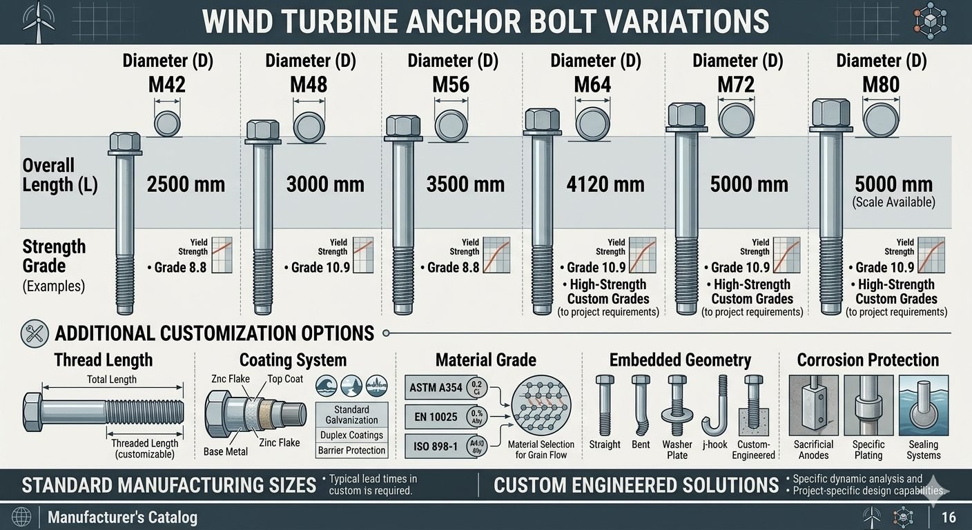
Wind Turbine Foundation Anchor Systems Design and Load Transfer Mechanics
In my two decades of heavy industrial and structural design practice, I have witnessed how towering renewable energy assets place unprecedented demands on sub-surface civil infrastructure. Wind turbine foundation anchor systems represent the critical mechanical and structural interface bridging dynamic superstructures with massive reinforced concrete substructures. When designing these anchorage assemblies, engineers must account for extreme multi-axial fatigue spectra generated by continuous aerodynamic rotor thrust and turbulent yaw misalignments.
Selecting the appropriate load transfer approach—whether through fully embedded tension bolts, post-tensioned anchor cages, or high-capacity anchor chairs—directly dictates overall steel consumption, constructability tolerances on site, and the long-term integrity of the installation. In this comprehensive technical guide, I examine the fundamental mechanical behavior, design methodologies, and practical trade-offs governing modern wind turbine foundation anchor systems.
Key Engineering Takeaways
- Cyclic wind fatigue requires rigorous adherence to ASCE and ACI 318 provisions for concrete breakout and bond stress capacity.
- Load transfer efficiency depends heavily on precise cage rigidity, grout compaction, and pre-load uniformity across all embedded bolts.
- Balancing steel consumption with constructability prevents costly on-site installation bottlenecks during multi-megawatt turbine erection campaigns.
Wind Turbine Foundation Anchor Systems Mechanics and Design Formulas
Designing wind turbine foundation anchor systems requires modeling the severe overturning moments transferred from the turbine tower flange down into the concrete foundation. The primary challenge lies in managing high tensile stresses on the windward side while simultaneously handling compressive bearing pressures on the leeward side. To evaluate the ultimate tensile capacity of embedded anchor bolts, structural engineers rely on the concrete capacity design method outlined in ACI 318 Chapter 17. The nominal concrete breakout strength in tension (N_cb) is determined using the basic equation:
In this formula, k_c represents the factor for cracked concrete, f_c’ is the specified compressive strength of concrete, h_ef is the effective embedment depth of the anchor, and A_Nc to A_Nc0 ratios account for anchor spacing and edge distance boundary restrictions. Modification factors psi account for edge effects, concrete state, and splitting influences. Ensuring adequate embedment depth prevents premature brittle cone pull-out failures.
Shear load transfer is another critical engineering domain. When lateral shear forces from wind and seismic events act on the tower base, they are transferred via friction at the baseplate-grout interface, direct bearing of anchor bolts against the concrete or sleeve, and dedicated shear lugs welded to the bottom of the anchor cage assembly. The nominal shear strength of anchors in concrete (V_sa) must be evaluated against pryout and concrete breakout failures as specified in governing wind energy codes.
Here, l_e is the load bearing length of the anchor in shear, d_a is the nominal anchor diameter, and c_a1 is the distance from the anchor axis to the free edge in the direction of the applied shear force. In large offshore and onshore multi-megawatt turbines, these calculated shear loads often exceed standard bolt capacities, necessitating heavy structural shear keys integrated into the foundation ring.
Engineering Warning: Fatigue Damage Accumulation
Wind turbine foundation anchor systems experience millions of load reversals over their operational design life of 20 to 25 years. Standard static design calculations are entirely insufficient. Engineers must perform comprehensive S-N curve fatigue analyses to prevent high-cycle fatigue cracking in threaded anchor rods and anchor cage welded nodes.
Inadequate bolt pre-tensioning significantly exacerbates stress range amplitudes, leading to accelerated bolt fatigue failure under operational bending moments. Always verify that tightening torque specifications comply with manufacturer tolerances and erection monitoring protocols.
Material selection for anchor assemblies must balance high tensile strength with adequate Charpy V-notch impact toughness, particularly in cold climate installations. High-strength alloy steels such as 42CrMo4 or ASTM A193 Grade B7 are frequently specified. However, hardness levels must be carefully controlled to prevent hydrogen embrittlement and stress corrosion cracking when exposed to alkaline concrete environments or moisture ingress through foundation grout joints.
Assembly geometry also dictates load distribution efficiency. Dual-ring anchor cages with intermediate stabilization templates ensure that individual bolts maintain verticality and spacing tolerances during continuous concrete mass pouring. Misalignment exceeding 1:40 can induce severe secondary bending stresses in the embedded shank, compromising the fatigue resilience of the entire foundation system.
Engineering Advantages
- Exceptional ultimate load capacity capable of transferring multi-megawatt overturning moments reliably.
- Continuous steel load paths minimize localized stress concentrations within the thick concrete pedestal ring.
- High fatigue resistance when proper bolt pre-tensioning and grouting protocols are strictly enforced on site.
- Post-tensioned anchor cage designs allow for better distribution of elastic strains across the massive concrete foundation mass.
- Standardized pre-fabrication of anchor cages ensures rapid on-site placement and reduces critical path construction schedules.
Engineering Disadvantages
- Extremely high structural steel consumption significantly increases raw material and fabrication project costs.
- Rigid geometric tolerances during concrete casting leave very little margin for construction error or bolt displacement.
- Complex logistical handling and heavy lifting requirements for large, pre-assembled anchor cage structures on remote sites.
- Risk of localized moisture entrapment and crevice corrosion within embedded sleeves or unbonded anchor lengths.
- Difficult and costly post-construction replacement procedures if a deeply embedded anchor bolt suffers fatigue failure.
Onshore Multi-Megawatt Wind Farms
Standard onshore installations utilizing 3MW to 6MW turbines require massive gravity-base foundations anchored by large dual-ring anchor cages. These systems transfer immense cyclic overturning moments into deep reinforced concrete pads while accommodating variable subsurface soil geotechnical profiles across expansive wind farm sites.
Offshore Fixed-Bottom Monopiles
Offshore fixed-bottom transition pieces rely on heavily bolted flange connections tied into underwater grouted or bolted foundation transition structures. The anchor systems must withstand aggressive marine environments, wave-current hydrodynamic slamming, and continuous aerodynamic fatigue loading over extended maintenance intervals.
Complex Mountainous Terrain Wind Projects
Ridge-line and complex terrain wind installations often encounter challenging sloped geotechnics and restricted spatial footprints. Rock-anchored gravity foundations utilize high-capacity post-tensioned rock anchors embedded directly into competent bedrock, requiring specialized socket design and corrosion protection layers.
Repowering and Upgraded Turbine Retrofits
Older wind energy sites undergoing structural repowering frequently install higher-capacity turbines onto legacy concrete foundations. Engineers deploy advanced post-installed anchor retrofits, high-strength chemical bonding agents, and structural strengthening collars to safely upgrade load transfer limits without replacing the entire below-ground concrete mass.
Wind Turbine Foundation Anchor Systems Design Parameters
Designing high-capacity anchorage setups for utility-scale wind turbine generators requires balancing structural stiffness, fatigue resistance, and constructability on site. Wind turbine foundation anchor systems experience severe cyclic overturning moments, eccentric shear forces, and fluctuating axial loads transmitted continuously from the tubular steel tower over a 20-to-25-year design life.
The following engineering data table outlines the core mechanical specifications, material grades, and operational thresholds governing embedded bolt assemblies, anchor cages, and post-installed post-tensioned tendon configurations as specified under ASCE Guidelines and international wind energy standards.
| Design Parameter | Embedded Bolt Assembly | Anchor Cage Ring System | Post-Tensioned Tendons |
|---|---|---|---|
| Primary Material Specification | ASTM A615 Gr. 75 / A354 BD | ASTM A572 Gr. 50 Structural Steel | ASTM A722 High-Strength Bar |
| Fatigue Resistance Threshold | Moderate to High (Requires preloading) | High (Rigid load distribution) | Superior (Constant stress range) |
| Installation Tolerance | Strict (+/- 2 mm template alignment) | Moderate (Factory welded cage rigidity) | Flexible (Grouted duct alignment) |
| Corrosion Protection Strategy | Hot-dip galvanizing / Epoxies | Embedded concrete alkaline cover | Grout encapsulation / Wax-filled ducts |
| Governing Failure Mode | Concrete breakout / Bond slip | Prying action / Plate yielding | Anchor pullout / Tendon relaxation |
Note: All values must be cross-verified against site-specific geotechnical reports and dynamic turbine loading spectra provided by the OEM.
Technical Mapping & Specifications Matrix
Complex structural interfaces within wind turbine foundations require rigorous entity mapping to ensure seamless load transfer from the dynamic tower steel shell down to the massive reinforced concrete gravity base. The following data matrix details the key structural components, associated material standards, and governing failure mechanisms analyzed during finite element design iterations.
Engineers must evaluate these entities in conjunction with ASCE / ACI 318 provisions for anchorage to concrete, ensuring that every load path component maintains adequate safety margins against cyclic fatigue degradation and concrete splitting.
| Entity / Component | Standard Reference | Primary Physical Parameter | Design Verification Focus |
|---|---|---|---|
| Embedded Anchor Bolt | ASTM A354 Grade BD | Tensile yield strength 130 ksi min | Fatigue stress range & concrete breakout |
| Anchor Cage Template Ring | ASTM A572 Grade 50 | Plate thickness 30 mm to 50 mm | Bending stiffness & bolt hole tolerance |
| Foundation Concrete Mass | ACI 318 Chapter 17 | Compressive strength 40 to 50 MPa | Cracking control & bearing pressure |
| Grout Interlayer Material | ASTM C1107 Non-shrink grout | Early compressive gain & flowability | Dynamic load transfer & void elimination |
| Reinforcing Steel Rebar | ASTM A615 Grade 60 | Yield strength 414 MPa nominal | Confinement steel & splitting resistance |
Matrix verification ensures full compliance with international wind turbine foundation design benchmarks.
Wind Turbine Foundation Anchor Systems Site Verification Checklist
Rigorous site quality control during the pre-pour and post-pour phases is mandatory to prevent costly structural remediation on multi-megawatt wind turbine installations. In my professional experience, neglecting anchor cage positioning tolerances or failing to verify proper consolidation of self-consolidating concrete around embedded assemblies leads directly to micro-cracking and premature fatigue failure under cyclic wind loads.
Use the following comprehensive site verification checklist to ensure strict compliance with engineering drawings, manufacturer tolerances, and international quality standards before concrete placement begins.
Pre-Pour & Installation Checkpoints
- ✓ Anchor Cage Elevation & Leveling: Verify that the upper anchor template ring is leveled within a tolerance of plus or minus 1.0 mm across the entire flange diameter using precision optical leveling equipment.
- ✓ Bolt Verticality & Plumbness: Check each embedded bolt for vertical alignment, ensuring deviation does not exceed 1:500 over the embedded length as mandated by ASCE standards.
- ✓ Template Rigidity & Bracing: Inspect internal steel bracing and temporary welded struts to guarantee the anchor cage cannot shift or distort during heavy concrete pumping and mechanical vibration.
- ✓ Thread Protection & Greasing: Ensure all exposed upper bolt threads are fully wrapped with heavy-duty protective sleeves and waterproof tape to prevent cement slurry splashing during the pour.
- ✓ Confinement Reinforcement Spacing: Confirm that hairpins, hoop steel, and supplementary bursting reinforcement around the anchor zone comply strictly with ACI 318 detailing rules.
- ✓ Concrete Slump & Workability: Verify that incoming mix trucks meet specified slump parameters and aggregate size limits for self-consolidating concrete to completely fill voids beneath base plates.
- ✓ Bond Breaker & Debonding Tubes: Check that debonding sleeves are correctly installed where required to control free bolt elongation length and optimize dynamic fatigue performance.
Any deviation identified during this verification process must be formally documented, reviewed by the lead structural engineer, and corrected prior to concrete truck dispatch.
Field Case Study: Real-World Application
Analyzing real-world engineering failures provides invaluable lessons for optimizing wind turbine foundation anchor systems in challenging onshore wind farm environments. The following case study details a critical alignment and fatigue challenge encountered during the construction of a 3.4 MW wind turbine installation on a complex geological site.
Problem Statement
Severe thermal expansion and inadequate temporary bracing during a mass concrete pour caused a 4-millimeter radial distortion in the upper anchor cage template ring, rendering standard tower flange bolting impossible.
- Concrete placement rate exceeded the temporary internal bracing design capacity by 35 percent.
- High ambient hydration temperatures induced thermal warping in the welded structural steel template assembly.
- Bolt plumbness drifted outside the strict plus or minus 2 mm tolerance required by the turbine manufacturer.
- Construction schedule pressure threatened to delay crane mobilization and tower erection milestones.
To resolve this critical site non-conformance without compromising the 20-year structural design life, an emergency engineering task force was mobilized immediately.
Case Outcome & Engineering Resolution
Implementing a precision-engineered corrective reaming procedure combined with high-strength epoxy-grouted sleeve adjustments restored full structural integrity and compliance with design codes.
- Conducted 3D laser scanning to map exact spatial coordinates of all 120 embedded anchor studs.
- Designed custom eccentric spherical washers approved under ASCE guidelines to accommodate minor angular misalignments safely.
- Performed finite element stress re-evaluations confirming that modified load paths maintained adequate safety factors against fatigue.
- Completed successful tension testing and final grouting within a strict 72-hour operational window, avoiding project delays.
Engineering Recommendation: For future utility-scale projects, always deploy rigid, modular, multi-tier steel template cages and monitor concrete pouring rates continuously to prevent thermal and mechanical distortion.
Frequently Asked Engineering Questions
What are the primary structural differences between anchor cage assemblies and ring plate anchor systems in wind turbine foundations?
- Anchor cages rely on individual high-strength threaded rods tied to top and bottom template rings, distributing tensile forces across a wide concrete footprint.
- Ring plate systems utilize a thick structural steel ring welded or bolted to the bottom of the anchor bolts, concentrating load transfer over a smaller, highly rigid plane.
- Cages offer better adjustability during installation, whereas ring plates provide superior fatigue resistance under cyclic wind shear stresses as outlined in DNV-ST-0126.
How do dynamic fatigue loads impact the required pretensioning of embedded foundation anchor bolts?
- High initial clamping force minimizes stress range fluctuations in the bolts as the turbine tower experiences varying wind thrusts.
- According to ASME PCC-1 guidelines, bolts must be tensioned to specific percentage thresholds to avoid joint separation under extreme gust events.
- Inadequate pretensioning accelerates thread stripping and fatigue crack propagation, severely reducing the operational lifespan of the foundation assembly.
What corrosion protection measures are mandated for post-installed versus cast-in-place anchor bolts?
- Cast-in-place bolts rely heavily on concrete alkalinity and secondary barrier coatings like hot-dip galvanizing or fusion-bonded epoxy.
- Post-installed chemical anchors require strict borehole cleaning protocols and moisture-insensitive epoxy resins compliant with ISO 12944 standards.
- Grout caps and specialized waterproof boot seals are routinely installed at the foundation interface to prevent moisture ingress at the tower flange.
How is concrete breakout failure calculated for closely spaced anchor groups under cyclic shear?
- Engineers apply ACI 318 Concrete Capacity Design (CCD) methodology to evaluate tensile and shear cone failures.
- Interaction equations must account for simultaneous bending moments, axial tension, and lateral shear forces transferred from the tower flange.
- If edge distances are restricted, supplementary reinforcement hairpins must be detailed to intercept potential breakout cracks and transfer loads safely.
What construction tolerances are required during the installation of large-diameter anchor cages?
- Upper template rings must maintain precise levelness and rotational orientation to prevent eccentric loading on individual bolts.
- Vertical plumbness of high-strength rods must be verified multiple times during mass concrete placement to avoid shifting caused by vibrator pressure.
- Thread protection sleeves are mandatory throughout the concrete pour to prevent slurry contamination and ensure proper post-pour fastener engagement.
Field Recommendation
As a practicing piping and structural engineering specialist overseeing wind farm civil interfaces, I advise applying the following rigorous project decisions during anchor system design and execution:
- If your turbine site experiences extreme turbulence intensities and high seismic activity, choose an anchor cage assembly with a bottom load transfer ring over a standard bolt-only setup because it prevents localized concrete crushing and distributes cyclic overturning moments more uniformly into the massive foundation core.
- When working with tight construction schedules, specify pre-assembled, factory-jigged anchor cages rather than loose site-assembled rods to eliminate vertical plumbness errors and eliminate costly delays during the critical mass concrete pour.
- Always mandate hydraulic tensioning over standard torque wrench tightening for all bolts exceeding 40 millimeters in diameter, as friction variations in large threads render torque-based preload calculations dangerously inaccurate under cyclic fatigue regimes.
- For coastal or highly corrosive onshore installations, upgrade the standard hot-dip galvanizing specification to a duplex coating system combined with an injected hydrophobic gel inside the anchor sleeves to guarantee a 30-year operational design life without premature bolt degradation.
Complete Course on
Piping Engineering
Check Now
Key Features
- 125+ Hours Content
- 500+ Recorded Lectures
- 20+ Years Exp.
- Lifetime Access
Coverage
- Codes & Standards
- Layouts & Design
- Material Eng.
- Stress Analysis
