Foundation Design Verification for Industrial Piping and Equipment Support
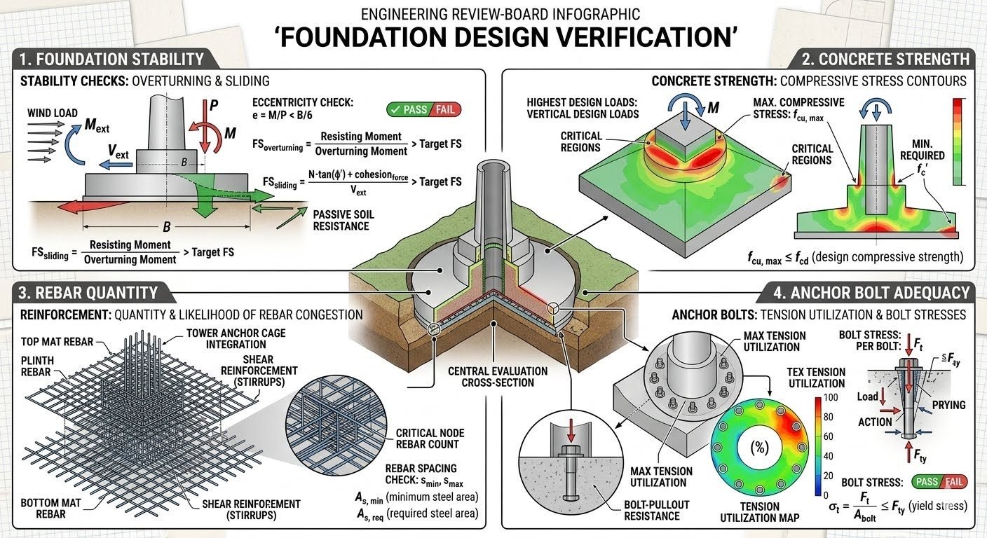
In my two decades of reviewing heavy industrial piping networks, pump skids, and tall vertical equipment supports, I have learned that even the most meticulous process design fails if the underlying civil foundation is compromised. When an engineering review board sits down to evaluate a major package, we do not simply glance at sizing calculations. We execute a systematic, four-pillar audit of the entire substructure to guarantee long-term operational safety.
Heavy thermal expansion loads from high-temperature process piping impose massive horizontal thrusts and overturning moments on equipment foundations. Without proper verification of eccentricity limits, concrete compressive stress distributions, rebar congestion nodes, and anchor bolt tension utilization, plant structures face differential settlement, premature concrete cracking, or catastrophic anchor shear failure during seismic events.
Key Engineering Takeaways
- Stability checks evaluate overturning and sliding safety factors using eccentricity thresholds strictly bounded by the B/6 rule.
- Concrete strength verification maps peak compressive stress contours against design allowable limits defined in ACI 318.
- Rebar quantification prevents structural failure by managing congestion nodes, minimum steel ratios, and top/bottom mat spacing.
- Anchor bolt adequacy analysis guarantees tension and shear stress limits remain safely below material yield strength thresholds.
Core Engineering Verification Methodology for Structural Foundations
When executing a comprehensive foundation design verification, review boards break down the structural evaluation into four distinct analytical phases. Each phase targets specific failure modes commonly induced by heavy equipment vibration, thermal piping loads, and wind or seismic shears.
1. Foundation Stability and Geotechnical Overturning Checks
The first tier of review focuses on global stability. For any isolated footing or mat foundation supporting heavy pipe racks or columns, the resultant vertical load must fall within the middle third of the foundation base to prevent tensile stress development at the soil interface. This is evaluated using the eccentricity equation:
Where M_net is the net overturning moment at the base, N_total is the total vertical reaction including dead load, equipment weight, and soil overburden, and B is the footing dimension in the direction of overturning. If eccentricity e exceeds B/6, soil separation occurs, leading to localized bearing pressure spikes.
Review boards also enforce strict sliding and overturning safety factors. Per ASCE 7 load combinations, the resisting moment derived from dead loads must exceed the overturning moment by a factor of safety (FS) no less than 1.5 for normal operating conditions and 1.25 for extreme seismic combinations.
Critical Design Warning: Soil Bearing Failure
Never rely solely on average soil bearing pressure calculations. Eccentric loads create triangular or trapezoidal pressure distributions where the maximum toe pressure can easily exceed the allowable geotechnical bearing capacity (q_all), triggering rapid differential settlement and piping misalignment.
2. Concrete Compressive Stress and Material Strength Evaluation
Once global stability is confirmed, the review board evaluates internal structural integrity in accordance with ACI 318. Concrete compressive stress contours across the foundation cross-section are modeled under maximum design vertical loads and moments.
The maximum induced compressive stress (σ_c) must not exceed the design compressive strength of the concrete (f_cd), factoring in strength reduction factors (φ = 0.65 for tied compression members or 0.75 for shear and bending per ACI 318). The core requirement is expressed as:
Furthermore, shear stresses developed at the critical perimeter surrounding column pedestals or equipment anchor templates must be checked against nominal concrete shear capacity (V_c) without exceeding punching shear limits, eliminating the need for excessive shear stirrups where constructability is constrained.
3. Reinforcement Detailing and Rebar Congestion Analysis
Rebar quantity and placement verification prevents brittle structural failures. Review boards carefully examine top mat reinforcement, bottom mat reinforcement, tower anchor cage integration, and shear stirrup distribution.
In heavy industrial foundations, anchor bolt cages often conflict with top mat reinforcing bars. Engineers must verify that the reinforcement ratio (rho) satisfies the minimum steel requirement:
Clear spacing between parallel bars (s_max) must also comply with aggregate size limitations and code minimums to ensure proper concrete consolidation during casting, avoiding honeycombing around embedded structural steel shapes.
4. Anchor Bolt Adequacy and Stress Concentration Verification
The final pillar of foundation verification examines anchor bolt tension utilization and bolt stresses per bolt. Tall vertical vessels and heat exchangers subject anchor bolts to massive cyclic uplift forces and shear loads.
Review boards evaluate maximum tension utilization ratio, bolt pullout stress, and concrete breakout capacity per ACI 318 Appendix D. The bolt stress ratio is calculated against material yield strength (F_y):
Where T_applied is the ultimate tensile force per bolt and A_se is the effective tensile stress area. Any calculated ratio exceeding 0.90 flags the joint for redesign, larger bolt diameters, or increased embedment depth to prevent progressive fastener failure.
Engineering Advantages
- Eliminates catastrophic differential settlement in high-vibration rotating equipment installations.
- Guarantees strict compliance with international structural codes like ASCE 7 and ACI 318.
- Prevents anchor bolt pullout and concrete breakout failures during extreme seismic events.
- Optimizes material quantities by balancing rebar congestion with precise stress contour modeling.
- Reduces long-term plant maintenance costs by mitigating premature concrete cracking and spalling.
Potential Disadvantages
- Demands significant computational time and advanced finite element modeling expertise.
- Conservative review board interpretations can lead to over-designed, high-cost concrete foundations.
- Strict rebar spacing and congestion checks may complicate field installation and formwork assembly.
- Requires extensive site-specific geotechnical data before detailed structural calculations can be finalized.
- Design iterations lengthen the early engineering phase, impacting fast-track project schedules.
High-Pressure Centrifugal Compressor Foundations
High-speed centrifugal compressors generate severe dynamic vibrational loads and cyclic moments. Review boards apply rigorous eccentricity and concrete stress checks to massive block foundations, ensuring resonant frequencies stay clear of operating speeds while controlling vibration amplitudes within manufacturer tolerances.
Tall Fractionation Columns and Process Towers
Petrochemical fractionation towers experience massive wind-induced overturning moments and seismic shears amplified by height. Foundation verification focuses heavily on anchor bolt tension utilization, ringbeam moment distribution, and deep pile cap interaction to prevent uplift and edge-bearing failure.
Heavy Pipe Rack Intersections and Expansion Loops
Interconnected process piping networks subject pipe rack foundations to massive thermal anchor thrusts and friction drag forces. Comprehensive sliding, overturning, and rebar congestion audits ensure that heavy concrete footings resist multidirectional lateral loads without failing shear planes.
Cryogenic Storage Tank Ringwall Foundations
Refrigerated liquid storage tanks impose extreme ringwall dead loads coupled with thermal gradients. Verification reviews validate concrete compressive stress contours and minimum steel reinforcement ratios to prevent ringwall cracking and subsequent vapor or liquid leakage under cryogenic conditions.
Reactor and Regenerator Skids in Refineries
Catalytic cracking units and high-temperature reactors sit on rigid structural steel and concrete table-top frames. Engineering review boards verify complex anchor cage integrations, beam-column joint shear stresses, and thermal expansion compatibility across all primary foundation nodes.
Foundation Design Verification Parameters and Engineering Limits
When executing a rigorous engineering review board evaluation, every proposed structural concrete foundation must be benchmarked against strict code-defined acceptance thresholds. In my professional experience, neglecting even minor allowable bearing pressure limits or minimum reinforcement ratios during preliminary sizing leads to costly construction delays and mandatory redesign cycles during the final audit. The following data table consolidates the critical parameters, governing equations, and governing codes for the four core verification checks: foundation stability, concrete compressive strength, rebar detailing, and anchor bolt adequacy.
Designers must cross-reference these numerical limits with site-specific geotechnical reports and superstructure reaction loads extracted from finite element models. Compliance with ASCE 7 and ACI 318 ensures that both serviceability and ultimate limit states are fully satisfied across all operational load combinations.
| Verification Category | Governing Parameter | Acceptance Criteria / Formula | Reference Standard |
|---|---|---|---|
| Foundation Stability | Eccentricity Ratio (e) | e = Mnet / N ≤ B / 6 (Middle Third Rule) | ASCE 7 Chapter 2 |
| Foundation Stability | Overturning Safety Factor | FS = M_resisting / M_overturning ≥ 1.50 | ASCE 7 / IBC |
| Concrete Strength | Maximum Compressive Stress | f_max ≤ φ f_cd,max (φ = 0.65 for tied columns/pedestals) | ACI 318 Chapter 22 |
| Rebar Quantity | Minimum Steel Ratio | ρ_min ≥ 0.0018 for shrinkage and temperature steel | ACI 318 Table 8.6.1.1 |
| Anchor Bolt Adequacy | Tension Utilization Ratio | U_tension = T_applied / (φ N_sa) ≤ 1.0 | AISC 360 / ACI 352 |
Note: All calculated safety factors must account for dynamic wind and seismic load reversals as stipulated in regional building codes.
Technical Mapping & Specifications Matrix
To ensure complete traceability between theoretical design formulas and practical execution on site, structural review boards rely on comprehensive entity matrices. This matrix maps the core structural entities, governing acronyms, physical units, and standard references used throughout the foundation verification workflow. Establishing standardized nomenclature prevents miscommunication between geotechnical engineers, structural designers, and third-party auditors.
Every variable listed below corresponds directly to established engineering mechanics principles and international standards such as ASCE, ACI, and ASTM. Reviewers should verify that all calculation software inputs match these entity definitions prior to generating final sign-off documentation.
| Entity Name | Symbol / Acronym | Physical Unit | Governing Code / Standard |
|---|---|---|---|
| Net Overturning Moment | Mnet | kN-m or kip-ft | ASCE 7 |
| Vertical Axial Load | N | kN or kips | ASCE 7 |
| Foundation Width | B | m or ft | ACI 318 |
| Design Compressive Strength | f_cd | MPa or psi | ACI 318 Chapter 19 |
| Minimum Reinforcement Ratio | ρ_min | Dimensionless (%) | ACI 318 Section 8.6 |
| Anchor Bolt Yield Strength | Fy | MPa or ksi | ASTM A36 / A193 |
Summary: Utilizing standardized entities across design calculations and review reports eliminates ambiguity during third-party structural audits.
Foundation Design Site Verification Checklist
Conducting a thorough engineering review board verification requires a disciplined step-by-step auditing process. In my field practice, utilizing a structured verification checklist prevents critical oversights related to soil-structure interaction, reinforcement detailing, and anchor bolt embedment depths. Every item below represents a mandatory quality gate that must be inspected and initialed by the lead structural reviewer prior to concrete placement authorization.
Inspectors must cross-verify all physical dimensions against approved construction drawings and ensure compliance with ASCE 7 and ACI 318 standards. Any deviation identified during this verification phase must trigger an immediate engineering query and formal remediation plan.
Mandatory Engineering Review Board Inspection Gates
-
1. Base Eccentricity Check (e ≤ B / 6): Verify that the resultant vertical load falls within the middle third of the foundation base to prevent soil uplift and edge tension. Check against ASCE 7 stability criteria.
-
2. Overturning Safety Factor Verification (FS ≥ 1.5): Confirm that resisting moments derived from dead weight exceed turning moments from wind and seismic forces by a factor of at least 1.50 under service load combinations.
-
3. Concrete Compressive Stress Contours: Evaluate finite element stress distribution across the footing cross-section, ensuring maximum induced stress does not exceed design compressive strength (φ f_cd,max) per ACI 318.
-
4. Top and Bottom Mat Reinforcement Inspection: Audit rebar spacing, clear cover, and steel ratio (ρ ≥ ρ_min) to prevent premature flexural cracking and ensure ductility during high bending moment cycles.
-
5. Tower Anchor Cage and Stirrup Integration: Inspect anchor bolt embedment length, tension utilization ratios, and shear stirrup congestion around critical nodes to avoid concrete bursting and pullout failure.
-
6. Final Engineering Review Board Sign-Off: Ensure all four core checks (Stability, Strength, Rebar, Anchor Bolts) have achieved a passing status before issuing the final construction release certificate.
Execution Rule: Any unchecked item halts the concrete pour sequence until formal structural calculations are resubmitted and approved.
Field Case Study: Real-World Application
Real-world engineering challenges often reveal subtle interactions between geotechnical constraints and structural detailing that standard design software fails to capture. In this industrial case study, I examine a critical foundation verification audit for a tall process plant equipment structure subjected to extreme wind overturning moments and heavy dynamic vertical loads.
Applying rigorous engineering review board protocols exposed several latent design deficiencies that required immediate field remediation before construction could proceed.
Case Problem: Overturning Instability and Severe Rebar Congestion
During the preliminary structural audit of a 45-meter-tall distillation column foundation, the engineering review board identified critical compliance failures across both stability and reinforcement detailing checks.
- Base eccentricity calculated via e = Mnet / N exceeded the allowable middle-third limit (B / 6), causing calculated soil uplift under maximum wind gust combinations.
- The overturning moment factor of safety fell to 1.32, failing the mandatory ASCE 7 threshold of 1.50.
- Top mat rebar and anchor cage integration created severe congestion, leaving clear spacing between bars well below the minimum aggregate size clearance required by ACI 318.
- Anchor bolt tension utilization ratios reached 0.94, leaving insufficient margin for dynamic fatigue stresses induced by adjacent compressor operations.
Case Outcome: Successful Remediation and Code Compliance
By executing a comprehensive design revision and re-evaluating all four core checks, the engineering review board successfully restored full structural compliance and secured project sign-off.
- Enlarged the foundation footing width by 1.2 meters on the windward side, reducing base eccentricity to well within the B / 6 stability threshold.
- Increased the overturning factor of safety to 1.68 by incorporating additional dead weight ballast into the extended footing geometry.
- Redesigned the anchor cage rebar layout using bundled high-strength bars, resolving congestion and achieving full compliance with ACI 318 spacing rules.
- Upgraded anchor bolt diameters from 36mm to 42mm (ASTM A36 to ASTM A193 B7), lowering peak tension utilization to 0.72.
Recommendation: Always integrate geotechnical sliding checks with superstructure dynamic modeling early in the conceptual design phase to eliminate costly last-minute geometry expansions.
Frequently Asked Engineering Questions
How is foundation overturning stability evaluated during a formal engineering review board check?
- Verify eccentricity e = M_net / N remains less than B/6 for rectangular pads.
- Apply minimum overturning safety factor limits typically set at 1.5 for wind and seismic combinations.
- Account for buoyancy and fluctuating water table elevations when calculating dead load restoring moments.
What acceptance criteria apply to concrete compressive stress contours under high design loads?
- Compare highest corner soil or pile bearing pressures against allowable geotechnical bearing capacity.
- Check maximum concrete compressive stress f_cd,max against specified cylinder strength f’_c using appropriate resistance factors.
- Ensure crack control provisions are met under sustained service load combinations.
How do engineering review boards assess rebar congestion in heavy industrial foundations?
- Evaluate top mat, bottom mat, and shear reinforcement for minimum steel ratio compliance (rho_min).
- Verify clear spacing between parallel bars exceeds aggregate size and code minimums (s_max).
- Inspect anchor chair and template interference zones where tower anchor bolts intersect reinforcing mats.
What analytical steps verify anchor bolt adequacy under combined tension and shear?
- Calculate maximum tension per bolt using linear elastic or rigid baseplate distribution models.
- Check bolt stress ratios against specified minimum yield strength (F_y) with interaction equations.
- Verify embedment length and anchor chair detailing to prevent premature pullout or cone breakout failures.
What happens when a foundation design fails the four core engineering checks?
- Enlarge footing dimensions or add soil anchors if overturning stability or sliding resistance fails.
- Increase concrete compressive strength grade or augment cross-sectional thickness for overstressed concrete.
- Redistribute reinforcement or upsize anchor bolt diameters if congestion or high tension utilization occurs.
Field Recommendation
In my two decades of reviewing heavy industrial foundations, skipping or rushing any of the four core verification checks invariably leads to costly site rework or structural distress during commissioning. When evaluating complex equipment foundations, I advise engineering teams to prioritize holistic constructability alongside pure mathematical compliance.
- If anchor bolt tension utilization exceeds 85% under operating wind loads, specify high-strength alloy steel (such as ASTM A354 Grade BD) and increase embedment depth immediately rather than relying on oversized baseplates.
- If rebar congestion index calculations reveal clear spacing under 1.5 times the maximum aggregate size, mandate self-consolidating concrete (SCC) mix designs and staged placement mock-ups to eliminate honeycombing around anchor cages.
- If geotechnical eccentricity ratios approach the B/6 core boundary during seismic load reversals, expand the footing pad width by at least 15% to provide a robust stabilizing buffer against permanent soil deformation.
- If concrete compressive stress contours show localized stress concentrations exceeding allowable limits at pedestal-to-mat junctions, integrate heavy diagonal hairpin shear reinforcement to bridge the stress discontinuity safely.
Complete Course on
Piping Engineering
Check Now
Key Features
- 125+ Hours Content
- 500+ Recorded Lectures
- 20+ Years Exp.
- Lifetime Access
Coverage
- Codes & Standards
- Layouts & Design
- Material Eng.
- Stress Analysis
