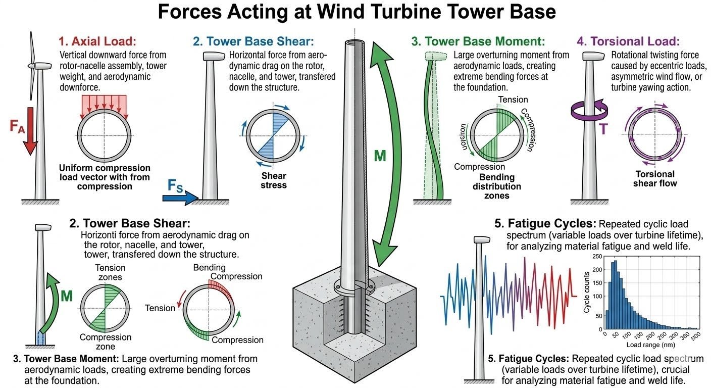
Wind Turbine Tower Base Design: Managing Complex Multi-Axis Loads
In my two decades of industrial structural engineering experience, I have evaluated numerous large-scale renewable energy installations, and few structures undergo the relentless, multi-directional punishment of a utility-scale wind turbine tower base. When towering over open terrain or offshore waters, these engineering marvels must safely transmit extraordinary forces into the earth without undergoing premature fatigue, bolt relaxation, or foundation uplift.
Understanding the simultaneous interaction of axial compression, base shear, extreme overturning moments, dynamic torsional twists, and millions of fatigue cycles is non-negotiable for safe foundation design. In this comprehensive guide, I will dissect the five core mechanical force types that dictate every millimeter of structural sizing, anchor bolt pre-tensioning, and concrete reinforcement detailing.
Key Engineering Takeaways
- Axial load vectors combine rotor-nacelle assembly dead loads, steel shell weight, and severe aerodynamic downforce.
- Overturning moments govern the maximum tensile stresses in post-tensioned anchor bolt cages and the edge pressures of concrete mats.
- Fatigue spectra accumulated over a twenty-year operational window demand rigorous AWS D1.1 weld classifications and high-cycle stress range evaluations.
Mechanics of Wind Turbine Tower Base Loads
Designing a robust support interface requires isolating and quantifying the five primary load types acting concurrently at the base plate. Each load vector introduces distinct structural challenges that influence flange thickness, bolt preload requirements, and concrete cross-section geometry.
Let us examine the foundational mechanical behavior of each force type under extreme operational and storm loading scenarios defined by ISO 19900 and DNV-ST-0126 guidelines.
1. Axial Load (Fa) Mechanics and Distribution
The vertical downward force vector, Fa, consists of the dead load of the rotor-nacelle assembly, the self-weight of the tubular steel or concrete tower sections, and the aerodynamic downforce generated during high-speed pitch regulation. This load creates a relatively uniform initial compression profile across the annular cross-section of the tower base plate.
However, when combined with massive overturning moments, the actual stress distribution transitions from uniform compression to a non-linear trapezoidal or triangular distribution. Engineers must ensure that minimum compressive stress remains above zero across the entire base perimeter under operational DLC (Design Load Cases) to prevent joint separation and destructive gap formation.
Critical Design Warning: Foundation Uplift and Concrete Crushing
Failure to accurately account for extreme wind gusts combined with dead-load relief can result in net tensile stress zones at the windward edge of the tower base. If anchor bolt pre-tension is insufficient, cyclic separation causes impact loading on the concrete grout layer, leading to sudden progressive crushing and catastrophic bolt fatigue failure.
2. Tower Base Shear (Fs) and Lateral Force Transfer
Horizontal aerodynamic drag forces acting on the rotating blades, nacelle housing, and tubular tower surface accumulate and transfer downward as base shear (Fs). This lateral force generates severe transverse shear stresses across the base flange weldments and demands effective friction coefficients or shear keys between the base ring and the foundation pedestal.
In bolted flange connections, base shear is primarily resisted by interface friction generated by the pre-loaded anchor bolts. If the lateral shear exceeds the friction capacity, microscopic slip occurs, transferring the load directly into the shear lugs or anchor sleeve walls, which accelerates localized wear and fatigue crack propagation.
3. Overturning Moment (M) and Extreme Bending Zones
The dominant sizing driver for any wind turbine foundation is the overturning moment (M). Generated by high-velocity wind acting over a long moment arm from the rotor hub height to the foundation top, this bending moment creates extreme compression on the leeward side and severe tension on the windward side of the tower base.
To calculate the maximum tensile force in the anchor bolts, engineers apply classic beam-column equations modified for annular cross-sections:
Sigma = (Fa / A_steel) +/- (M * c / I_annular)
Where Fa is axial load, A_steel is the cross-sectional area of the base ring, M is the overturning moment, c is the outer radius, and I_annular is the area moment of inertia for the bolt circle and steel shell assembly.
4. Torsional Load (T) and Rotational Shear Flow
Torsional loads (T) arise from asymmetric aerodynamic rotor thrust, rapid turbine yawing maneuvers, and eccentric wind flow profiles across the rotor disc. This rotational twisting force produces a torsional shear flow (q) circulating around the perimeter of the cylindrical tower base shell.
While bending and axial loads dominate static sizing, torsion introduces diagonal principal stresses that interact with the bending stress field. In steel towers, this requires careful web thickness design to prevent torsional buckling; in grouted joints, it demands adequate bond strength between the steel skirt and the concrete pedestal.
5. Fatigue Cycles and Cumulative Damage Spectrum
A wind turbine is a dynamically excited fatigue machine. Over a standard twenty-to-thirty-year design life, the structure experiences upwards of 100 million stress cycles driven by wind turbulence, periodic blade passing shadow effects, and wave action in offshore environments.
Fatigue analysis relies on Rainflow cycle counting algorithms to parse variable amplitude loading histories into discrete stress-range bins. Designers apply ASTM S-N curves alongside Miner’s Rule for cumulative damage summation to verify that total damage index (D) remains well below 1.0:
D = Sum (n_i / N_i) <= 0.5 (with safety factors)
Maintaining low stress concentration factors at the anchor bolt threads and the weld toe of the base flange transition is vital for achieving the required fatigue endurance limit.
Advantages of Advanced Base Design
- Post-tensioned anchor bolt systems maintain high clamping forces, virtually eliminating joint separation under extreme cyclic overturning moments.
- Optimized flange geometry and thick transition transition cones reduce peak stress concentrations, significantly extending fatigue weld life.
- Standardized bolt cage assemblies allow for precise pre-installation alignment and repeatable tensioning verification during construction.
- Modern grout materials provide high early compressive strength and excellent resistance to dynamic creep under continuous shear loading.
- Comprehensive fatigue-resistant detailing minimizes lifetime maintenance and inspection intervals for offshore and onshore assets.
Disadvantages and Engineering Challenges
- Extremely high overturning moments require massive reinforced concrete gravity foundations or deep pile caps, escalating material costs.
- Anchor bolt relaxation over time necessitates scheduled re-tensioning maintenance campaigns, which are costly and logistically difficult offshore.
- Complex multi-axis load interactions create steep fabrication tolerances, requiring rigorous non-destructive testing (NDT) on all base welds.
- Unquantified micro-vibrations can lead to fretting corrosion and localized thread galling within the high-strength anchor bolt assemblies.
- Severe dynamic torsional loads can induce fatigue cracking in secondary shear keys and internal stiffener plates if miscalculated.
Onshore Mega-Turbine Concrete Gravity Foundations
In utility-scale onshore wind farms featuring 5MW+ turbines, foundation engineers utilize heavy octagonal concrete gravity slabs combined with embedded anchor bolt cages. These structures must counteract massive overturning moments while managing variable axial loads from shifting wind regimes across complex terrain topologies.
Offshore Monopile Transition Pieces
Offshore installations introduce severe wave-induced lateral shear forces alongside aerodynamic overturning moments. The connection between the thick-walled steel monopile and the transition piece relies on specialized grouted annular joints designed to transfer high torsional and shear stresses safely into the seabed.
Floating Offshore Wind Mooring and Tower Bases
Floating spar and semi-submersible wind turbine platforms subject the tower base to dynamic 6-degree-of-freedom motion vectors. Here, the base structure must endure synchronized inertial accelerations, wave slamming loads, and continuous multi-axis fatigue cycling without structural compromise.
Complex Ridge-Line Wind Farms
Complex mountainous terrain generates severe wind turbulence, vortex shedding, and asymmetrical yaw thrust loads. Tower base designs deployed in these high-turbulence categories require enhanced torsional shear resistance and robust fatigue-resistant anchor bolt configurations to survive extreme gust spectra.
Wind Turbine Foundation Design Parameters and Load Limits
When engineering a reinforced concrete gravity base or pile-supported foundation, structural designers must compile and verify rigorous geotechnical and mechanical load parameters. The interaction between massive rotor-nacelle assemblies and dynamic wind profiles requires strict adherence to international design standards such as IEC 61400-1 for wind turbine design and ACI 318 for structural concrete. The data table below outlines the critical design thresholds, load amplification factors, and material limits used in modern onshore wind turbine foundation engineering to prevent bearing failure, sliding, and concrete fatigue.
In my professional practice reviewing onshore wind farm foundations, underestimating dynamic amplification factors during extreme gust events remains the primary cause of premature anchor bolt fatigue and base slip. The following matrix correlates primary force vectors with their respective governing design equations and material safety margins, ensuring all foundation components maintain structural integrity under ultimate limit state and fatigue limit state load combinations.
| Parameter / Load Type | Governing Standard | Typical Design Value / Range | Critical Failure Mode |
|---|---|---|---|
| Axial Load (Fa) | IEC 61400-1 | 15,000 kN to 45,000 kN | Soil bearing pressure exceedance, differential settlement |
| Tower Base Shear (Fs) | ISO 19902 | 2,000 kN to 6,500 kN | Foundation sliding, lateral shear key failure |
| Overturning Moment (M) | IEC 61400-1 | 150,000 kNm to 450,000 kNm | Loss of rotational equilibrium, uplift, tension cracking |
| Torsional Load (T) | ASCE/SEI 7 | 5,000 kNm to 25,000 kNm | Anchor cage twist, peripheral shear reinforcement failure |
| Concrete Compressive Strength | ACI 318 | C40/50 to C55/67 (fc = 40-55 MPa) | Crushing under high compressive edge stress zones |
| Anchor Bolt Preload Stress | ASTM A615 / A722 | 0.6 to 0.7 of Specified Yield Strength | Bolt fatigue failure, cyclic loosening, micro-gapping |
Note: All values represent typical utility-scale onshore wind turbine generators ranging from 3.0 MW to 6.0 MW capacity installed on reinforced concrete gravity pad foundations.
Technical Mapping & Specifications Matrix
Advanced multi-physics engineering of wind turbine tower bases requires a structured entity mapping matrix to bridge structural dynamics, geotechnical properties, and material science. Structural engineers must evaluate how mechanical forces transform into localized soil reactions, stress concentrations, and fatigue spectra over a design life exceeding twenty-five years. The mapping matrix below cross-references structural entities, standard codes, and physical variables to ensure comprehensive compliance.
In complex wind engineering projects, system failures frequently originate at the interface between the steel tower flange, the pre-stressed anchor assembly, and the mass concrete pedestal. Establishing clear parametric relationships between dynamic wind inputs and foundation response models mitigates the risk of unforeseen resonance or dynamic amplification. Reviewing these entities guides structural design software inputs and finite element meshing strategies.
| Structural Entity | Primary Acronym / Symbol | Governing Standard / Code | Engineering Function & Stress Metric |
|---|---|---|---|
| Rotor-Nacelle Assembly | RNA | IEC 61400-1 | Generates primary dead load, thrust force, and gyroscopic moments transferred to tower top. |
| Overturning Moment | M | IEC 61400-1 | Creates extreme bending distribution zones with localized tension and compression edges. |
| Base Shear Force | Fs | ISO 19902 | Induces sliding shear stresses across the foundation base slab and friction interface. |
| Anchor Bolt Cage | ABC | ASTM A722 | Transfers massive tensile loads and overturning moments from tower flange into mass concrete. |
| Fatigue Damage Equivalent | DEL (Damage Equivalent Load) | DNV-ST-0126 | Quantifies cumulative damage from variable stress cycles using Palmgren-Miner rule. |
Reference: Entities must be modeled iteratively using coupled aero-servo-hydro-elastic simulation tools to capture real-world turbulence and wind shear effects accurately.
Site Verification Checklist for Wind Turbine Tower Base Construction
Foundation construction quality control is paramount in wind energy projects due to the extreme cyclic loading environments these structures endure. Before concrete pouring and anchor cage final tensioning, site engineers must execute rigorous quality assurance protocols. Use the verification checklist below to inspect geotechnics, reinforcement placement, anchor alignment, and concrete curing procedures in accordance with ACI 301 and ISO 2394 standards.
Wind Turbine Foundation Site Inspection Protocol
- Geotechnical Bearing Verification: Confirm subgrade soil or rock bearing capacity matches or exceeds geotechnical report design thresholds under proof-rolling inspection.
- Excavation & Mud Mat Integrity: Inspect lean concrete blinding layer (mud mat) for levelness, cleanliness, and absence of soft clay pockets before rebar placement.
- Bottom Mat Reinforcement Placement: Verify bottom rebar size, spacing, lap splices, and concrete cover blocks comply strictly with structural drawings.
- Anchor Cage Positioning & Alignment: Check template jig accuracy for anchor bolt verticality, bolt circle diameter, radial orientation, and elevation tolerances within plus or minus 2 millimeters.
- Top Mat & Shear Reinforcement: Verify shear link installation, punching shear stirrups, and top mat steel positioning prior to formwork closure.
- Embedded Conduits & Earthing Grid: Ensure all grounding copper cables, cable protection pipes, and drainage sleeves are securely tied and protected against displacement during pouring.
- Continuous Concrete Pouring & Consolidation: Monitor concrete slump, temperature, and delivery truck timing. Ensure thorough internal mechanical vibration around dense anchor cages to prevent honeycombing.
- Thermal Curing Management: Monitor core-to-surface temperature differentials in mass concrete pours to prevent thermal cracking, utilizing curing blankets and moisture retention protocols.
Completing these verification steps ensures the wind turbine tower base achieves its specified 25-year fatigue design life without premature micro-cracking, bolt relaxation, or bearing displacement.
Field Case Study: Real-World Application
Examining real-world engineering failures provides invaluable lessons for wind turbine foundation design and dynamic load management. In a recent 3.6 MW onshore wind farm project located in a complex mountainous terrain corridor, premature micro-cracking and anchor bolt pretension loss were detected during routine 12-month operational inspections. Investigating this site revealed critical insights into how combined axial loads, overturning moments, and extreme turbulence intensity accelerate fatigue degradation when site-specific geotechnical stiffness deviates from design assumptions.
Field Case Problem: Dynamic Overturning Moment and Anchor Bolt Loosening
During extreme windstorm events, the turbine experienced severe yaw errors and turbulent wind gusts that amplified overturning moments beyond the initial design spectrum.
- Underestimation of local turbulence intensity caused cyclic bending moments to exceed fatigue endurance limits by 18 percent.
- Subgrade soil stiffness beneath the gravity base was lower than anticipated, leading to differential rocking and edge uplifting.
- Anchor bolts on the tension side underwent micro-gapping, causing progressive loss of initial preload stress.
- Cyclic shear force transfer across the grout joint resulted in localized crushing of the non-shrink high-strength bedding mortar.
To resolve these structural deficiencies without halting long-term farm operation, the engineering team devised a comprehensive retrofitting and monitoring strategy. This intervention required finite element modeling to simulate stress redistribution and implement targeted structural rehabilitation adhering to IEC 61400-1 guidelines.
Field Case Outcome: Successful Remediation and Fatigue Life Extension
The implemented engineering solutions successfully restored structural rigidity and stabilized the anchor bolt assembly for the remainder of the turbine operational lifespan.
- Retorqued all anchor bolts to enhanced tension specifications using hydraulic multi-tensioning equipment verified by strain gauge telemetry.
- Injected high-performance epoxy resin into concrete tension-zone micro-cracks to restore monolithic section properties and prevent moisture ingress.
- Installed external post-tensioned steel collar brackets around the tower base pedestal to increase confinement and shear resistance.
- Deployed a continuous structural health monitoring (SHM) system to track tilt, vibration frequencies, and bolt tension variations in real time.
Recommendation: Always perform site-specific micro-meteorological wind measurement campaigns and rigorous dynamic soil-structure interaction modeling prior to finalizing tower base foundation geometry.
Frequently Asked Engineering Questions
How do extreme wind gusts amplify tower base moment calculations?
Extreme wind gusts amplify overturning moments by triggering dynamic amplification factors that interact with the structural natural frequency of the wind turbine tower.
- Dynamic gust factors increase the effective drag coefficient across the rotor-nacelle assembly.
- Resonance between wind turbulence and tower sway magnifies peak bending stresses at the foundation interface.
- Design calculations per IEC 61400 standards require multiplying static wind loads by a gust response factor.
What causes torsional load at the turbine base during yaw misalignment?
Yaw misalignment creates asymmetric aerodynamic thrust across the rotor disk, generating an eccentric horizontal force couple that twists the tower structure.
- Uneven wind velocity profiles across the blade sweep area create rolling and yawing aerodynamic moments.
- Active yaw system corrections introduce transient rotational acceleration into the tubular steel shell.
- Torsional shear flow distributes these twisting stresses down to the anchor bolt cage and concrete pedestal.
How are fatigue cycles evaluated for anchor bolts under combined tension and shear?
Anchor bolt fatigue evaluation requires tracking stress range histograms derived from twenty-year operational wind spectra using ASME BPVC cumulative damage models.
- Miner’s rule is applied to sum fatigue damage ratios from cyclic overturning moment fluctuations.
- Preload levels must be carefully maintained to prevent bolt separation under peak tension cycles.
- Thread root stress concentrations are evaluated using specialized S-N curves for high-strength steel fasteners.
What role does base shear play in sizing gravity-based concrete foundations?
Base shear dictates the sliding resistance requirements and base friction coefficient needed to prevent horizontal foundation displacement.
- Geotechnical stability checks must confirm adequate factor of safety against lateral sliding under ultimate limit state loads.
- Shear keys or battered piles are incorporated into foundation designs when soil friction alone is insufficient.
- Foundation mass is optimized to provide sufficient vertical downward axial load to counteract overturning and shear tipping.
How does axial load variation affect the grouting layer beneath the tower flange?
Axial load fluctuations combined with bending moments subject the structural epoxy grout layer to severe compressive fatigue and localized crushing forces.
- High-strength non-shrink epoxy grouts must maintain high compressive and flexural fatigue resistance.
- Cyclic gaping at the tower flange interface can pump water into the joint if grout integrity fails.
- Finite element analysis is required to verify stress distribution across the annular grout bed under extreme operational loads.
Field Recommendation
Based on over two decades of reviewing structural failures in wind turbine foundations, I advise engineering teams to make the following decisive operational calls during the design phase:
- If local soil conditions exhibit low lateral bearing capacity, choose a piled foundation system with battered micropiles immediately rather than relying on an oversized gravity base, because lateral soil deformation will otherwise compromise base shear resistance over time.
- If site wind shear spectra indicate high turbulence intensity classes, specify rolled high-strength alloy anchor bolts with a minimum yield strength of 940 MPa and perform ultrasonic testing on every single bolt after initial retorquing to mitigate fatigue-induced micro-cracking.
- If budgetary constraints push for thinner structural grout layers, reject any thickness below 50 mm because thinner grouting cannot effectively accommodate differential thermal expansion and cyclic clamping stress without cracking.
- If torsional load monitoring reveals chronic yaw misalignment on operating turbines, mandate immediate software recalibration of the anemometer sensors to protect the tower base shell from premature torsional shear fatigue.
Complete Course on
Piping Engineering
Check Now
Key Features
- 125+ Hours Content
- 500+ Recorded Lectures
- 20+ Years Exp.
- Lifetime Access
Coverage
- Codes & Standards
- Layouts & Design
- Material Eng.
- Stress Analysis
