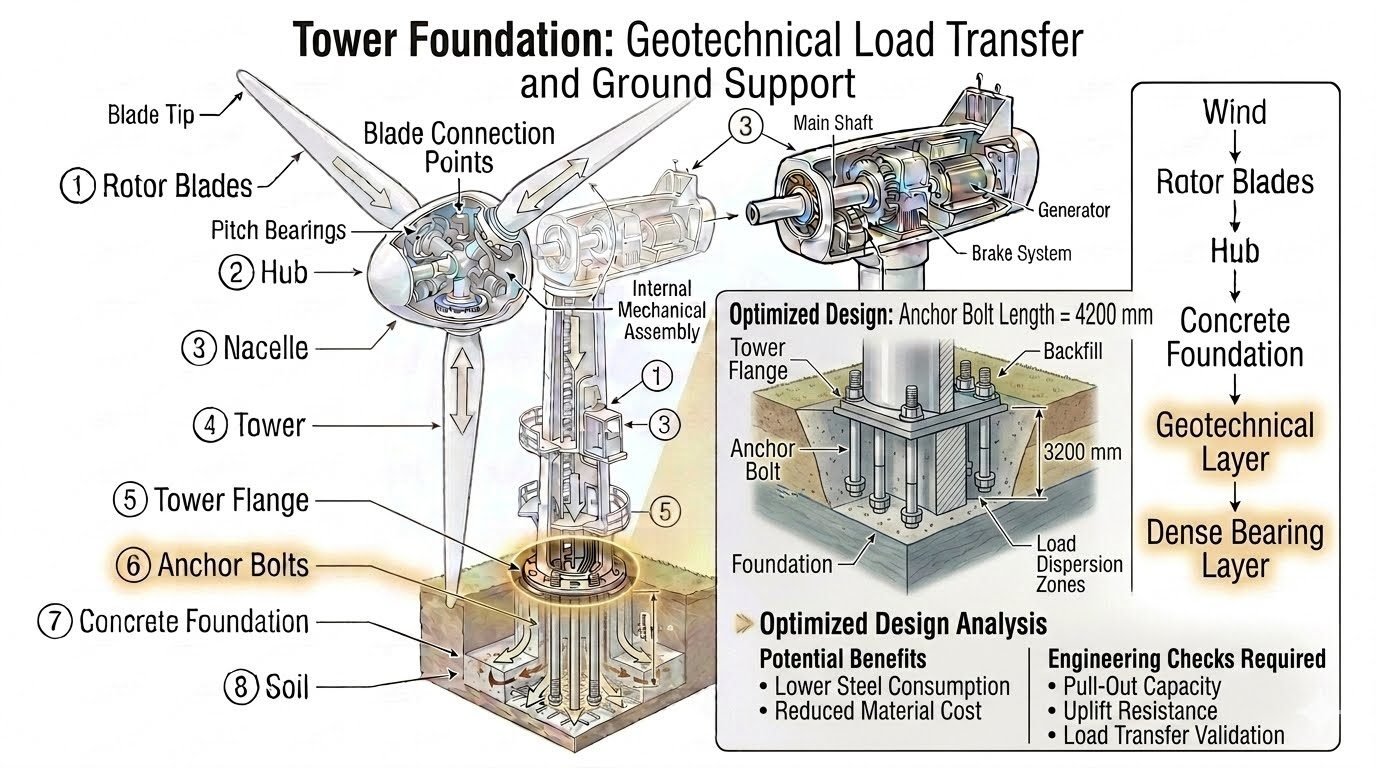
Optimized Anchor Bolt Length for Structural Foundations
In my two decades of managing heavy industrial piping and foundation design projects, I have frequently encountered the temptation to trim material expenses by shortening embedded structural components. When an optimized foundation design reduces anchor bolt length from an original value to 4200 mm, the engineering team must immediately look past initial capital expenditure savings.
Changing the depth to which the bolt is embedded within the backfill and foundation directly alters how mechanical forces interact with the surrounding soil and concrete matrices. Relative to the load dispersion zones beneath heavy machinery and tall towers, any arbitrary reduction in embedment can shift critical stress cones into unreinforced or vulnerable foundation strata.
This optimized design analysis identifies potential benefits of lower steel consumption and reduced material cost, but requires four specific engineering checks before implementation: pull-out capacity, uplift resistance, and load transfer validation.
Key Engineering Takeaways
- Embedment reduction to 4200 mm requires verifying concrete breakout cones.
- Steel consumption savings must be weighed against severe cyclic fatigue risks.
- Rigorous validation protects against catastrophic uplift and pull-out failures.
Structural Mechanics of Optimized Anchor Bolt Length
When evaluating an optimized foundation design reduces anchor bolt length from an original value to 4200 mm, you must first understand the fundamental mechanics governing load transfer into concrete pedestals. Anchor bolts do not merely hold equipment down; they form a complex load-sharing composite with the surrounding cementitious matrix and reinforcement cage.
In standard foundation configurations, longer bolts distribute tensile and shear stresses over a broader volume of concrete. Shortening the assembly concentrates these reaction vectors into a tighter geometric envelope, increasing local bearing pressures directly beneath the anchor head or anchor plate.
According to ACI 318 Chapter 17 provisions for anchoring to concrete, the nominal concrete breakout strength in tension is a direct function of the embedment depth raised to the power of 1.5. Reducing the embedment length to 4200 mm causes a non-linear drop in tensile breakout capacity, which must be offset by increased steel diameter, altered layout geometry, or upgraded concrete compressive strength.
Mathematical Modeling of Concrete Breakout Capacity
The basic equation for nominal concrete breakout strength of a single anchor in tension is expressed as:
In this formulation, h_ef represents the effective embedment depth. When h_ef is reduced to 4200 mm, the term h_ef^1.5 decreases significantly. If the unreduced design relied on a deeper embedment to clear lower reinforcement layers, the new 4200 mm depth might place the critical failure cone entirely within unreinforced zones or intersecting secondary rebar mats.
This geometric shift requires the piping and structural engineer to verify that the projected breakout failure surface does not intersect free edges or neighboring anchor stress zones. Overlapping failure cones drastically reduce collective group efficiency.
Interaction of Backfill Stiffness and Foundation Restraint
Anchor bolts embedded across the interface of structural concrete foundations and compacted backfill experience complex lateral restraint conditions. A length of 4200 mm often positions the critical embedment zone precisely at the boundary where the rigid monolithic pedestal transitions to flexible soil subgrades or compacted granular backfill.
Differential settlement between the massive concrete block and the surrounding backfill induces secondary bending moments along the shaft of the anchor bolt. If the bolt is shortened, its unsupported or partially supported length changes relative to the fixity point, altering its natural frequency and vulnerability to resonant vibrations from attached rotating equipment such as centrifugal compressors or large pumps.
Critical Safety Warning: Fatigue and Cyclic Shear
Shortened anchor bolts subjected to reciprocating machinery loads exhibit higher localized strain amplitudes at the concrete interface. Neglecting high-cycle fatigue checks under shortened embedment conditions can lead to sudden, brittle fatigue failure of the steel rod even when static tensile stresses remain well below allowable yield limits.
Load Transfer Validation Protocols
To ensure structural safety, the transition of forces from the baseplate, through the leveling nuts or grout pad, and into the 4200 mm anchor bolt must satisfy rigorous equilibrium checks. The load transfer validation phase requires checking three distinct mechanical pathways:
- Direct Bearing Transfer: Verifying that baseplate anchor chairs and leveling plates prevent localized crushing of the non-shrink grout layer.
- Bond Stress Distribution: Calculating local bond-slip relationships along deformed bars or embedded headed studs to ensure slip does not exceed serviceability limits.
- Side-Face Blowout Resistance: Confirming that edge distances are adequate to prevent concrete side-face blowout when high tensile preloads are applied to the shortened shads.
By systematically working through these verification steps, engineering teams can safely capture the economic benefits of reduced steel consumption without compromising the long-term structural reliability of heavy industrial foundations.
Advantages of Optimization
- Substantial reduction in raw material procurement costs for high-strength alloy steel rods.
- Decreased foundation excavation depth and reduced volume of structural blinding concrete.
- Lighter cage assemblies that are easier to pre-fabricate, lift, and position accurately on site.
- Shorter installation times during critical path foundation pouring phases.
- Reduced formwork pressures during concrete placement around shallower bolt cages.
Disadvantages & Risks
- Lower overall pull-out capacity requiring rigorous non-linear finite element verification.
- Increased sensitivity to installation tolerances and misalignment during casting.
- Higher localized concrete bearing stresses requiring larger baseplates or stiffeners.
- Reduced margin of safety against unexpected seismic or extreme wind overturning moments.
- Potential necessity to upgrade concrete mix design strength (f’c) to compensate for reduced embedment.
Refinery Process Column Foundations
Tall distillation columns and fractionator towers experience severe wind-induced overturning moments and seismic shear forces. Optimizing anchor bolt embedment to 4200 mm in these mega-foundations requires careful management of annular anchor bolt chairs and continuous post-tensioning monitoring.
Engineers utilize precise finite element analysis to ensure the shortened bolts maintain adequate fatigue life despite cyclic vortex-shedding forces acting on the tall shell.
Offshore Topside Module Skids
Weight control is a paramount economic and safety driver in offshore platform design, where every ton of top-side dead load directly impacts floating hull buoyancy and mooring requirements. Shortening structural tie-down anchor bolts to optimized depths trims critical dead weight without sacrificing typhoon-load resistance.
Specialized corrosion-resistant coatings and rigorous pull-out verification protocols are mandatory in these marine environments to guarantee long-term joint integrity.
Heavy Compressor Skids in Gas Plants
Reciprocating and centrifugal compressors generate intense dynamic vibrations that transmit high-frequency cyclic loads directly into the concrete block foundation. Optimizing anchor bolt sizing and embedment to 4200 mm helps balance elasticity requirements, preventing excessive vibration transmission while minimizing expensive alloy steel usage.
Dynamic compliance checks per ASME standards ensure that the shortened bolt assembly does not tune into operating frequency harmonics.
Power Generation Turbine Pedestals
Steam and gas turbine islands require massive, highly rigid concrete mass foundations to maintain shaft alignment under extreme thermal and mechanical operating loads. Implementing optimized anchor lengths around high-temperature turbine casings demands meticulous thermal growth calculations.
Differential thermal expansion between the steel anchor bolts and the surrounding concrete matrix must be accommodated to prevent thermal binding or loss of bolt preload.
