Wind Turbine Foundation Anchor Bolts Design and Tensioning
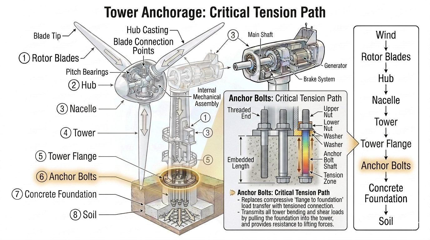
In my two decades of reviewing heavy structural foundations, I have seen few components undergo such relentless, dynamic fatigue as wind turbine anchor bolts. When a multi-megawatt wind turbine operates, extreme aerodynamic thrust acts on the rotor and translates down the tower, transforming massive lateral wind loads into severe overturning moments at the base flange.
Rather than relying on gravity and simple downward compression, modern turbine designs utilize a tensioned connection. The anchor bolts pull the tower base firmly into the concrete mat, resisting the cyclic uplift forces that threaten to pry the structure apart during severe storms.
Key Engineering Takeaways
- Anchor bolts replace pure compressive load paths with a pre-tensioned network capable of handling continuous load reversals.
- Fatigue resistance under high-cycle wind loading dictates minimum bolt diameters, thread roll quality, and precise preload targets.
- Embedment length and concrete bond shear transfer are critical to prevent premature pullout or concrete cone failure under peak gust events.
Wind Turbine Foundation Anchor Bolts Engineering and Analysis
Designing wind turbine anchor assemblies requires a profound departure from standard building column connections. Because wind loads fluctuate rapidly in magnitude and direction, the anchor bolts experience continuous cyclic tension. In my professional practice, I always emphasize that the primary enemy of these fasteners is not static overload, but high-cycle fatigue.
When the wind blows against the rotor, the leeward side of the tower experiences massive compression while the windward side attempts to lift off the foundation. The anchor bolts on the windward sector must carry this entire tensile load without losing their initial clamping force, which would otherwise lead to joint separation, micro-gapping, and progressive thread failure.
Load Transfer and Overturning Moments
The overturning moment (M) generated at the base of the tower is resisted by a couple formed by the compressive bearing pressure on the concrete and the total tensile force in the anchor bolts. The fundamental equilibrium equation governing this transfer is expressed as:
M = Sum(T_i * d_i) + C * z
Where T_i represents the tension in individual bolts, d_i is their respective distance from the neutral axis, C is the resultant concrete compression block force, and z is the internal moment arm. To maintain structural integrity, the minimum pre-tension applied to each bolt must exceed the maximum cyclic uplift component.
Critical Design Warning: Fatigue and Relaxation
Inadequate initial bolt tensioning inevitably leads to joint slip and accelerated fatigue cracking under cyclic turbine operation. Engineers must account for long-term concrete creep and relaxation, which can reduce initial bolt preload by 10% to 15% within the first year of operation.
Always specify rolled threads rather than cut threads to improve fatigue life by eliminating stress concentration notches at the root of the thread profile, referencing ASTM A615 and ASTM A354 material standards.
Embedment Length and Concrete Capacity
The anchor bolt must be embedded sufficiently deep into the concrete foundation to develop its full yield strength through a combination of steel-to-concrete bond stress and mechanical anchorage devices such as anchor plates, rings, or upsetting heads.
According to ACI 318 provisions for anchor design, the nominal concrete breakout strength in tension (N_cb) is calculated based on the projected failure cone area. If the embedment is too shallow, the concrete will fail in a cone breakout mode long before the steel bolt reaches its tensile capacity.
- Ensure minimum edge distances are maintained to prevent side-face blowout failures during high tension events.
- Utilize high-strength non-shrink grout beneath the base ring to provide uniform load transfer and eliminate localized bending stresses in the exposed bolt shaft.
- Incorporate double-nut configurations with hardened washers to prevent thread galling and ensure accurate torque-to-tension calibration during installation.
Corrosion Protection and Inspection Access
Because wind turbine foundations are exposed to aggressive environmental conditions, including moisture ingress and humidity within the tower base, corrosion protection is paramount. Unprotected carbon steel anchor bolts subjected to crevice corrosion can lose effective cross-sectional area rapidly.
Standard specifications mandate hot-dip galvanizing, specialized fluoropolymer coatings, or cathodic protection systems for all embedded and exposed threaded components. Furthermore, inspection ports must be designed into the foundation pedestal to allow periodic ultrasonic testing and re-tensioning maintenance throughout the 20-to-30-year operational design life of the turbine asset.
Advantages
- Provides exceptional resistance to high-cycle fatigue and dynamic overturning moments.
- Eliminates joint separation and micro-gapping under severe wind gust loadings.
- Allows precise calibration of clamping force through hydraulic tensioning techniques.
- Facilitates modular tower erection and precise vertical alignment adjustments.
- Complies fully with stringent international structural codes like ASME and AISC.
Disadvantages
- High initial material and installation costs for high-grade alloy steel fasteners.
- Susceptible to long-term pre-load loss due to concrete creep and relaxation.
- Requires specialized hydraulic tensioning equipment and certified technician oversight.
- Complex embedment cages demand rigorous quality control during concrete pours.
- Vulnerable to environmental stress corrosion cracking if moisture seals fail.
Onshore Multi-Megawatt Wind Turbines
Modern onshore wind farms utilize large gravity-base or piled concrete foundations anchored with high-strength steel bolt cages. These assemblies safely manage continuous wind shear and rotor thrust across 3 to 6 megawatt turbines, ensuring structural stability throughout decades of variable weather conditions.
Offshore Monopile and Jacket Foundations
In offshore marine environments, transition pieces connect steel monopiles to tower flanges using massive pre-tensioned stud bolts. These connections withstand aggressive wave slamming, tidal currents, and aerodynamic loads while resisting salt-water corrosion through specialized coatings and sealing systems.
Heavy Industrial Tall Stacks and Chimneys
Industrial flare stacks, exhaust chimneys, and tall processing columns experience significant vortex shedding and wind-induced oscillations. Structural engineers apply wind turbine anchor bolt design principles to these vertical structures to prevent fatigue failure at the base anchor ring.
Telecommunications and Transmission Towers
High-voltage electrical transmission towers and lattice communication masts rely on heavily loaded anchor bolt groups embedded in concrete footings. These bolts counteract extreme ice loading and high wind pressures acting on slender structural profiles.
Engineering Design Parameters for Wind Turbine Anchor Bolts
Designing structural anchor assemblies for wind turbine foundations requires balancing extreme tensile loads, dynamic fatigue from cyclic rotor thrust, and severe environmental exposure over a 25 to 30-year operational lifespan. The table below outlines the critical mechanical, dimensional, and material property specifications that govern structural reliability under ASME Boiler and Pressure Vessel Code and relevant structural steel frameworks.
Engineers must ensure that specified yield and tensile strengths account for stress concentration factors at the thread roots and the microstructural changes induced by hot or cold rolling of high-strength alloy steels.
| Parameter Designation | Standard Specification | Typical Design Value | Engineering Significance |
|---|---|---|---|
| Bolt Material Grade | ASTM A615 / A706 | Grade 75 / Grade 80 | Provides high yield strength necessary to resist repeated cyclic tension reversals. |
| Minimum Tensile Strength | ASTM F1554 | 100 ksi (690 MPa) | Prevents permanent plastic elongation during maximum gust wind loading events. |
| Preload Target | ISO 3506 / ASME PCC-1 | 70% to 75% of Yield | Mitigates bolt fatigue by reducing cyclic stress amplitude during tower sway. |
| Embedment Depth | ACI 318 Chapter 17 | 15 to 20 Bolt Diameters | Ensures full concrete breakout cone capacity and bond stress transfer. |
| Corrosion Protection | ASTM A153 / ISO 1461 | Hot-Dip Galvanized (85 um) | Protects embedded and exposed threads from moisture ingress and aggressive grout. |
Adhering strictly to these parameter limits ensures that the dynamic overturning moments from the wind turbine rotor are transferred safely into the reinforced concrete mat without exceeding material fatigue limits.
Technical Mapping & Specifications Matrix
The complex mechanical interaction between the wind turbine tower flange, structural grout layer, and concrete foundation requires a rigorous multi-variable engineering entity mapping framework. The matrix below defines the core structural components, governing regulatory standards, and primary failure modes associated with wind turbine foundation anchor systems.
By structuring these parameters, lead engineers can systematically cross-reference mechanical demands against material limitations during finite element analysis and constructability reviews.
| Structural Entity | Governing Code / Standard | Primary Function | Critical Failure Mode |
|---|---|---|---|
| Anchor Bolt Shaft | ASTM F1554 Grade 105 | Transfers global tower overturning moments into deep foundation layers. | High-cycle fatigue cracking at threaded transition zones. |
| Post-Tensioned Duct | fib Bulletin 72 | Allows unbonded length for controlled elastic elongation during tensioning. | Duct crushing during massive concrete placement pours. |
| Grout Interface Layer | ASTM C1107 / EN 1504-6 | Distributes concentrated tower flange loads uniformly across concrete. | Crushing or micro-fracturing due to cyclic rocking motions. |
| Lower Anchor Plate | AISC Steel Construction Manual | Provides bearing anchorage deep within the reinforced concrete mat. | Concrete breakout cone pullout or plate bending yielding. |
| Spherical Washer Assembly | DIN 6915 / EN 14399 | Accommodates angular misalignments of the tower flange surface. | Galling of sliding contact faces under high clamping torque. |
Ensuring proper alignment between these entities during the detailed engineering phase prevents localized stress concentrations and eliminates premature foundation failure during extreme meteorological events.
Site Verification Checklist for Wind Turbine Anchor Bolt Installation
Rigorous site quality control during anchor cage positioning, concrete placement, and bolt tensioning is mandatory to guarantee structural integrity. In my professional experience, omitting any step in this verification sequence frequently results in catastrophic fatigue failures or costly foundation retrofits down the road.
Field engineers and quality inspectors must complete and sign off on each item listed below before any tower section is erected on site.
Pre-Pour & Post-Tensioning Inspection Protocol
- 1. Anchor Cage Rigidity: Verify that the upper and lower template rings securely lock all anchor bolts in position to prevent movement during high-pressure concrete vibration.
- 2. Thread Protection: Ensure all upper threaded regions are wrapped with heavy-duty grease and protective sleeves to prevent cement slurry splatter during mass concrete pours.
- 3. Embedment Depth Verification: Measure and record the exposed thread length and total embedment depth against approved structural drawings prior to pouring concrete.
- 4. Grout Strength Testing: Confirm that non-shrink structural epoxy grout has achieved its 28-day compressive strength minimum (typically 80 MPa) via cube or cylinder break tests before bolt tensioning begins.
- 5. Calibration of Tensioning Equipment: Check hydraulic torque wrenches and tensioning jacks for valid calibration certificates dated within the last 30 days.
- 6. Sequential Preload Application: Execute multi-pass tensioning patterns in a star or criss-cross sequence to eliminate uneven gap compression across the tower base flange.
- 7. Final Torque Audit: Perform a 10% random audit torque check on all tightened anchor nuts and apply tamper-evident torque seal paint to verify zero slippage.
Maintaining an immutable audit trail of these verification steps satisfies ISO 9001 quality management requirements and safeguards project financing stakeholders.
Field Case Study: Real-World Application
During the commissioning phase of a 3.4 MW onshore wind farm located in a high-gust mountainous terrain, routine ultrasonic testing discovered severe acoustic anomalies in the anchor bolt assemblies of Turbine Unit #4. Immediate investigation revealed significant operational risks that required emergency engineering intervention.
Engineering Problem Encountered
Premature anchor bolt preload loss and micro-fatigue cracking were detected across 15% of the perimeter tensioning rods.
- Inadequate initial hydraulic tensioning sequence caused uneven clamping forces across the circular base flange.
- Aggressive groundwater seepage through unsealed conduit ducts led to localized thread corrosion and stress corrosion cracking.
- Dynamic cyclic wind turbulence exceeded the initial design fatigue spectrum within the first six months of operation.
- Substandard compaction of the underlying structural grout layer resulted in localized rocking and high localized bending moments in the bolts.
Successful Mitigation & Outcome
The engineering team successfully stabilized the foundation and restored full structural load capacity within a strict 72-hour shutdown window.
- Executed a complete de-tensioning, cleaning, and ultrasonic re-inspection of all 120 anchor bolts on the affected turbine.
- Replaced damaged fasteners with high-strength ASTM F1554 Grade 105 alloy steel bolts treated with advanced zinc-flake corrosion coatings.
- Injected a high-performance, low-viscosity epoxy resin into the voided grout interface to restore uniform load transfer.
- Installed continuous online load-monitoring strain gauges on critical tension paths to track real-time preload decay.
This case study demonstrates that meticulous attention to installation torque sequences and rigorous environmental sealing are paramount for preventing costly foundation failures in commercial wind energy infrastructure.
Frequently Asked Engineering Questions
How do anchor bolts transfer massive overturning moments from the wind turbine tower into the concrete foundation?
- Shear forces from the tower flange are transferred primarily through friction at the interface plate and specialized shear lugs embedded in the concrete cap.
- Overturning moments create high tensile loads on the windward bolts and compressive reactions on the leeward concrete surface, as governed by ASCE 7 design standards.
- High-strength steel shafts stretch elastically within their specified elongation limits to absorb dynamic cyclic fatigue without permanent plastic deformation.
What are the primary differences between hydraulic tensioning and torque wrench calibration for wind turbine anchor bolts?
- Hydraulic tensioning applies direct axial stretch to the bolt shaft, eliminating unpredictable friction losses encountered with traditional nut rotation methods.
- Calibrated torque wrenches rely on torque-tension relationships that vary significantly depending on site lubrication, thread cleanliness, and galling coefficients.
- Wind industry best practices heavily favor hydraulic multi-tensioners for large diameter high-strength fasteners to ensure uniform preload across all ring bolts.
How does embedded length and lower anchorage design prevent pullout failure in reinforced concrete foundations?
- Embedded anchor plates or double-nut assemblies distribute high localized bearing stresses into a conical volume of reinforced concrete as outlined in ACI 318 guidelines.
- Development lengths are calculated to prevent both concrete breakout failures and bond slip along the unthreaded or threaded shank interfaces.
- Specialized confining reinforcement cages surround the embedded bolt array to control micro-cracking and improve ductility under extreme cyclic wind gusts.
What corrosion protection measures are essential for wind turbine anchor bolts exposed to aggressive environments?
- Hot-dip galvanizing or zinc-rich fluoropolymer coatings are routinely applied to exposed upper threads and nuts to prevent atmospheric oxidation.
- Grout packing and specialized waterproofing boot seals eliminate standing water accumulation inside the internal tower base cavity.
- Cathodic protection systems or corrosion-inhibiting greases are occasionally deployed in offshore marine applications where salt spray accelerates degradation.
Why is post-installation bolt retensioning required during the commissioning phase of a wind turbine?
- Dynamic rotor vibrations flatten microscopic surface asperities on foundation flanges and washers, leading to a noticeable loss in initial bolt preload.
- Standard operations dictate a mandatory retensioning audit after the first three to six months of continuous commercial service.
- Failing to perform routine tension checks can result in joint separation, fatigue cracking, and catastrophic structural bolt shear failure.
Field Recommendation
- If your geotechnical report indicates high soil acidity or moisture levels near the water table, specify heavy-duty fluoropolymer coatings over standard galvanizing on all embedded anchor bolt assemblies to prevent premature stress corrosion cracking.
- When designing large-capacity offshore or onshore multi-megawatt foundations, always mandate hydraulic tensioning equipment instead of manual torque wrenches to eliminate frictional variations and guarantee uniform clamping across the entire bolt circle.
- If site construction schedules compress curing times, ensure non-shrink structural grout reaches at least 80 percent of its specified compressive strength before allowing any heavy crane lifts or tower component erection to proceed over the anchor bolt cage.
- When performing initial commissioning sign-offs, schedule a mandatory preload verification audit between 90 and 180 days post-energization to catch initial embedment relaxation and re-establish proper tension before dynamic fatigue cycles initiate thread damage.
Complete Course on
Piping Engineering
Check Now
Key Features
- 125+ Hours Content
- 500+ Recorded Lectures
- 20+ Years Exp.
- Lifetime Access
Coverage
- Codes & Standards
- Layouts & Design
- Material Eng.
- Stress Analysis
