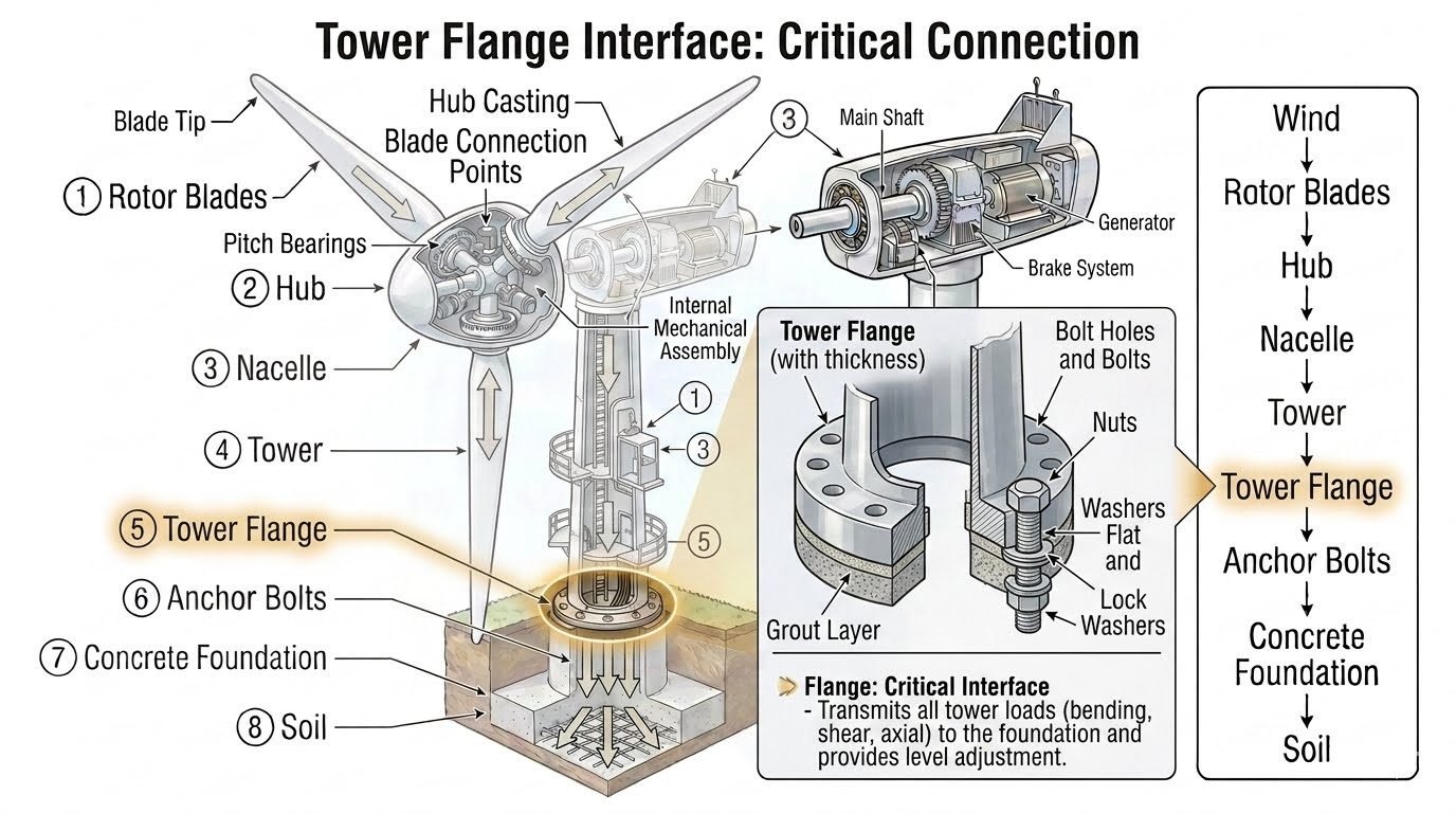
Engineering Tower Flange Design: Foundation Interface Standards
In my twenty-plus years designing structural connections for heavy industrial and renewable energy infrastructure, I have repeatedly observed that the interface between the above-ground steel tower and the below-ground concrete foundation is the most vulnerable stress concentration zone in the entire assembly. When you examine a utility-scale wind turbine, the tower flange bears the brunt of cyclic aerodynamic thrust, gravitational eccentricities, and seismic accelerations. Designing this critical joint requires a meticulous balance of high-strength structural bolting, exact flange thickness profiles, and non-shrink cementitious or epoxy grout layers.
Throughout this guide, I will walk you through the rigorous mechanical principles, tightening protocols, and material standards required to eliminate fatigue failures and uplift separations at the foundation interface. Adherence to established codes such as ASME BPVC Section VIII and AISC Steel Construction Manual is non-negotiable for achieving a reliable 25-year operational design life.
Key Engineering Takeaways
- Tower flange thickness must be engineered to prevent localized prying action and excessive out-of-plane distortion.
- Preload verification using calibrated hydraulic tensioning is mandatory to mitigate cyclic fatigue and bolt relaxation.
- High-performance non-shrink grout layers ensure uniform pressure distribution across the entire foundation concrete surface.
Tower Flange Structural Mechanics and Design Parameters
The structural integrity of a wind turbine foundation interface relies entirely on how effectively the tower flange converts multi-axial aerodynamic loads into uniform compressive stresses within the concrete pedestal. As wind flows past the rotor blades, it creates a massive overturning moment coupled with high lateral shear forces. This moment translates into extreme cyclic tension on the windward side bolts and compressive intensification on the leeward side. To prevent joint opening, which rapidly accelerates fatigue degradation, engineers must specify adequate flange thicknesses and precise bolt preloading schedules in accordance with ISO 2394 reliability principles.
When calculating the required flange thickness, standard elastic plate theory often underestimates localized bending deformations between adjacent bolt holes. I always mandate finite element modeling (FEM) to analyze out-of-plane flange curling. If the flange plate is too thin, the application of bolt tension causes the outer rim to lift slightly, concentrating contact pressure on the inner bolt circle and inducing severe prying forces. According to ASME PCC-1 guidelines for pressure boundary bolted flange joint assembly, managing bolt scatter and maintaining parallel gap tolerances are essential to preserving gasket or metal-to-metal contact integrity.
Critical Design Warning: Flange Prying and Fatigue
Failure to account for dynamic prying action in high-capacity tower flanges leads directly to progressive bolt fatigue snapping. Wind turbines experience millions of load reversals; therefore, design calculations must incorporate a minimum dynamic amplification factor (DAF) of 1.35 on peak overturning moments, combined with rigorous S-N curve validations per DNV-ST-0126 standards.
Advanced Bolt Preload and Tensioning Methodologies
Achieving the specified clamping force in heavy structural bolts (typically M36 to M64 in grade 10.9 or 12.9 carbon steel) cannot be left to traditional torque wrenches alone due to high friction coefficients. In my field practice, I exclusively specify hydraulic tensioning for initial elongation, followed by calibrated nut rotation where torque control is unavoidable. The target preload must typically reach 70 to 75 percent of the bolt material yield strength.
The multi-pass tensioning sequence is critical to prevent uneven gasket or concrete seating. Technicians must execute a minimum of four distinct passes crossing diagonally in a star pattern:
- Pass 1: Apply 30 percent of the final target load to seat the washers and flatten minor surface imperfections.
- Pass 2: Increase load to 60 percent to establish preliminary joint parallelism.
- Pass 3: Apply 100 percent of the calculated target tension across all primary foundation anchor studs.
- Pass 4: Perform a mandatory verification pass 24 hours later to compensate for initial relaxation and embedding loss.
Grout Layer Mechanics and Load Transfer Efficiency
Beneath the steel tower flange lies the structural grout layer, serving as the crucial transition medium between steel and concrete. Because cast-in-place concrete foundations can never achieve the millimetric flatness required for a heavy metal flange, the grout layer bridges this gap. It must possess exceptionally high compressive strength (minimum 80 MPa at 28 days) and negligible drying shrinkage to prevent void formation.
Epoxy-based grouts are frequently preferred over cementitious grouts in harsh offshore or high-vibration onshore environments due to their superior dynamic load absorption and chemical resistance. During installation, formwork must be sealed tightly, and head boxes installed on the high side to facilitate continuous gravity flow or pump injection. Any entrapped air pockets beneath the flange will create stress concentrations, leading to localized crushing of the grout pad and subsequent rocking of the entire wind turbine tower structure.
Engineering Advantages
- Precise Leveling Adjustments: The space beneath the flange allows leveling nuts and grout thickness tuning to guarantee true vertical tower alignment.
- Disassemble and Replace: Unlike embedded anchor cages, bolted flange rings permit complete tower dismantling or retrofitting during repowering cycles.
- Uniform Load Distribution: A properly tensioned bolt ring combined with high-strength grout spreads overturning moments evenly into the concrete foundation.
- Standardized Fabrication: Steel flanges can be precision-machined in controlled workshop environments, ensuring exact hole pitch diameter and surface flatness.
- Clear Inspection Access: External bolts, nuts, and grout lines remain fully accessible for routine visual and ultrasonic non-destructive testing (NDT).
Engineering Disadvantages
- Fatigue Susceptibility: Cyclic aerodynamic wind loading creates severe alternating stresses in bolts, demanding rigorous torque and tension maintenance.
- High Installation Precision: Grout mixing, pouring, and curing require strict ambient temperature control and skilled technicians to avoid voids.
- Corrosion Vulnerability: The foundation interface zone is prone to moisture accumulation, requiring robust protective coatings and perimeter sealing systems.
- Material Cost Intensity: Heavy forged steel sections, high-grade alloy studs, and specialized epoxy grouts contribute to significant capital expenditure.
- Complex Bolt Relaxation: Initial embedment relaxation requires mandatory retightening campaigns, increasing commissioning labor overhead.
Onshore Utility-Scale Wind Turbines
Modern 3MW to 6MW onshore wind turbines utilize massive base tower flanges bolted directly to reinforced octagonal concrete gravity foundations. The flange transfers immense cyclic bending moments generated by rotor sweeps while maintaining strict verticality tolerances required by internal mechanical drivetrains.
Offshore Monopile Transition Pieces
In offshore wind installations, the transition piece flange connects the submerged steel monopile to the above-water tower structure. These flanges operate in aggressive marine environments, requiring specialized cathodic protection, heavy-duty epoxy grouting, and corrosion-resistant fasteners to withstand wave slam and wind action.
Telecommunication and Transmission Masts
Self-supporting lattice and tubular communication towers rely on heavy base flanges anchored to deep concrete pier foundations. The foundation interface must accommodate high torsional wind loads and dynamic vibrations without experiencing anchor slip or base plate fatigue cracking.
Industrial Flare Stacks and Chimneys
Industrial flare stacks in petrochemical facilities utilize robust anchored base flanges to withstand thermal expansion stresses and high-velocity wind vortex shedding. Precision grout layers ensure even load distribution across heavily reinforced ring foundations subjected to continuous operational vibration.
Offshore Oil and Gas Platform Flares
Marine platform flare booms and vertical support columns incorporate heavy bolted flange interfaces welded to structural deck girders. These connections are engineered to endure severe wave impact, salt spray corrosion, and extreme cyclonic wind forces with zero structural slip.
Tower Flange Design Parameters and Mechanical Properties
Tower flange connection assemblies demand rigorous adherence to mechanical property thresholds to withstand cyclic wind shear and overturning moments. The structural integrity of the steel-to-concrete interface depends heavily on grade selection, yield strength matching, and controlled pre-loading across all structural fasteners. In my professional practice, reviewing material test reports (MTRs) against ASME Section II and ASTM International standards prevents catastrophic fatigue failures.
The engineering data table below outlines the critical mechanical parameters governing heavy industrial tower flange assemblies, anchor bolts, and structural interface materials. Every parameter listed must be verified during the procurement and factory acceptance testing (FAT) phases.
| Component Layer | Material Specification | Min. Yield Strength | Governing Standard | Key Inspection Metric |
|---|---|---|---|---|
| Tower Base Flange | ASTM A572 Gr. 65 / S355ML | 450 MPa (65 ksi) | ASME BPVC / EN 10025 | Ultrasonic testing (UT) for laminations |
| Foundation Anchor Bolts | ASTM A354 Grade BD / 10.9 | 850 MPa (130 ksi) | ASTM A354 / ISO 898-1 | Magnetic particle inspection (MPI) |
| Heavy Hex Nuts | ASTM A563 Grade DH / 10 | Proof Load: 120 ksi | ASTM A563 / ISO 4032 | Thread engagement and hardness check |
| Structural Flat Washers | ASTM F436 / Hardened Steel | 38 HRC Surface Hardness | ASTM F436 | Parallelism and thickness verification |
| Non-Shrink Interface Grout | Cementitious / Epoxy Blend | 80 MPa Compressive (28d) | ASTM C1107 / EN 1504-6 | Flow cone test and cube crushing |
Note: All specified fastener torques and tensions must incorporate calculated friction coefficients derived from approved anti-seize lubricants.
Technical Mapping & Specifications Matrix
Complex wind turbine support structures rely on multidisciplinary engineering integration, bridging structural steel design, geotechnical foundation mechanics, and advanced materials science. Establishing an accurate entity data matrix ensures that design consultants, site supervisors, and quality control inspectors share a unified technical vocabulary. When evaluating interface connections, tracing the relationship between physical loads and material responses prevents structural overstressing.
The mapping matrix below correlates structural entities with their primary engineering functions, failure modes, and applicable design codes. Referencing these parameters during design reviews guarantees full compliance with international wind energy safety standards.
| Entity / Parameter | Structural Function | Primary Failure Mode | Governing Standard |
|---|---|---|---|
| Overturning Moment (Mz) | Transfers wind-induced rotor thrust into foundation | Bolt fatigue failure and flange prying | ISO 19901-3 / IEC 61400-1 |
| Pre-tensioning Force (Fp) | Clamps tower flange securely to grout and concrete | Bolt relaxation and cyclic strip-out | RCSC / AISC Specification |
| Grout Layer Transfer | Eliminates micro-gaps and ensures uniform stress | Crushing, voids, or freeze-thaw spalling | ASTM C1107 / ACI 351.1R |
| Shear Key Interface | Resists lateral horizontal sliding loads | Shear friction failure of concrete | ACI 318 Building Code |
Entity mapping must be cross-verified with finite element analysis (FEA) models to account for dynamic amplification factors.
Site Verification Checklist for Tower Flange Installation
Rigorous on-site quality control during the erection phase dictates whether a wind turbine foundation interface achieves its 25-year design life. Field engineers must execute systematic sign-offs at every milestone, from initial foundation leveling to final torque verification. Skipping verification steps often leads to uneven load distributions and localized stress concentrations that compromise the structural integrity of the entire tower.
The following structured checklist establishes mandatory verification protocols for site engineers. Use these criteria during pre-installation, grouting, and final bolt tensioning operations to maintain absolute compliance with engineering specifications.
Phase 1: Foundation Surface & Leveling Preparation
- Verify concrete foundation curing time has reached minimum 75 percent design compressive strength (typically 7-14 days).
- Chisel and sandblast foundation top surface to remove laitance, oil, and loose aggregate, ensuring adequate bonding.
- Check leveling nut elevations across all anchor bolt locations using a digital optical level to within plus or minus 1.0 mm.
Phase 2: Tower Flange Placement & Grout Injection
- Lower tower base flange onto leveling nuts, verifying vertical plumbness with dual-axis laser transits.
- Inspect formwork sealing around the base perimeter to prevent grout leakage during pressure pumping.
- Pour and tamp non-shrink cementitious grout continuously from one side to eliminate air pockets beneath the flange plate.
Phase 3: Fastener Tensioning & Final Sign-Off
- Apply calibrated hydraulic torque or tensioning in three sequential passes (30%, 70%, 100%) following a star pattern.
- Verify final bolt elongation or torque values with an independent quality control inspector using calibrated tools.
- Apply anti-corrosion paste and thread sealing compound to all exposed fastener threads and washer assemblies.
All completed checklist items must be signed and archived in the permanent wind farm construction quality dossier.
Field Case Study: Real-World Application
Real-world engineering challenges often test the limits of standard design assumptions, requiring rapid diagnostic assessment and corrective intervention. During a routine 5-year operational audit on a 3.4 MW onshore wind farm located in a high-turbulence mountainous region, significant bolt relaxation and localized grout degradation were identified at the tower flange interface of Turbine Number 14.
Problem Statement
Inspections revealed a 1.2 mm gap beneath the tower flange baseplate accompanied by acoustic emission signatures indicating intermittent fastener micro-slippage under extreme wind gust loading.
- Cyclic dynamic overturning moments exceeded initial tightening torque projections over 60 months of operation.
- Poor early-stage grout consolidation created internal voids, leading to localized crushing under high compressive loads.
- Thermal expansion coefficient mismatches between the steel flange and sub-base grout induced severe shear stresses.
- Inadequate re-torque maintenance cycles allowed primary anchor bolts to drop below 80 percent of specified preload.
Outcome & Resolution
Implementing a comprehensive structural remediation plan restored full load-transfer capacity and eliminated dynamic joint deflection within 72 hours.
- Hydraulic jacking elevated the tower base by 4 mm to permit complete high-pressure epoxy grout re-injection.
- All 120 primary anchor bolts were replaced with upgraded ASTM A354 Grade BD fasteners tensioned to exact yield thresholds.
- Installed continuous online strain-gauge monitoring to track real-time bolt load retention and dynamic bending moments.
- Established an accelerated biannual re-torque and ultrasonic bolt inspection protocol across all regional turbines.
Recommendation: For similar high-turbulence installations, site operators should mandate ultrasonic bolt load verification every 12 months rather than relying solely on manual torque wrench checks.
Frequently Asked Engineering Questions
What is the primary structural function of a tower flange in wind turbines?▼
- Transfers massive bending moments generated by rotor aerodynamic thrust forces.
- Transmits heavy axial dead loads and dynamic fatigue cycles down to the pedestal.
- Provides micro-adjustment leveling capabilities during initial erection phases.
Why is precision bolt tensioning critical for high-capacity foundation interfaces?▼
- Prevents micro-gapping between flange rings during extreme gust events.
- Eliminates cyclic stress concentrations that cause premature fatigue fracture.
- Guarantees uniform clamp stress distribution across the entire bolt circle diameter.
What role does the non-shrink grout layer play beneath the tower flange?▼
- Eliminates localized high-stress point loads on the concrete pedestal surface.
- Provides chemical resistance against moisture ingress and freeze-thaw degradation.
- Distributes compressive deadweight uniformly across the complete foundation footprint.
How do engineers prevent corrosion in embedded or exposed foundation anchor bolts?▼
- Hot-dip galvanizing or specialized fluoropolymer coatings on exposed threads.
- Weatherproofing boots filled with corrosion-inhibiting grease compounds.
- Continuous drainage design to prevent standing water accumulation on the flange.
What inspection methods verify tower flange integrity during scheduled maintenance?▼
- Ultrasonic testing of anchor studs to detect subsurface stress corrosion cracking.
- Torque and tension re-checking on a sampling of critical high-stress bolts.
- Visual inspection of grout edges for micro-cracking, spalling, or staining.
Field Recommendation
Drawing from my extensive field experience commissioning multi-megawatt wind turbine foundations, I advise engineering teams to make the following precise technical judgments during project execution:
- If your site experiences high seismic activity or severe wind shear turbulence, specify hydraulic tensioning over standard torque wrenches to eliminate frictional variations and guarantee uniform 80 percent proof-load retention across all anchor studs.
- When placing under-flange structural grout in sub-zero or high-temperature ambient conditions, reject standard cementitious mixes and mandate temperature-controlled epoxy resin grouting to prevent early shrinkage cracks and maintain dynamic load transfer integrity.
- If routine ultrasonic testing reveals initial micro-cracking in the root radius of the steel tower flange, immediately implement acoustic emission monitoring rather than waiting for scheduled turbine downtime to prevent catastrophic fatigue propagation.
- When designing coastal or offshore splash-zone installations, pair hot-dip galvanized ASTM A354 fasteners with impressed current cathodic protection to halt accelerated crevice corrosion at the concrete-steel interface.
Complete Course on
Piping Engineering
Check Now
Key Features
- 125+ Hours Content
- 500+ Recorded Lectures
- 20+ Years Exp.
- Lifetime Access
Coverage
- Codes & Standards
- Layouts & Design
- Material Eng.
- Stress Analysis
