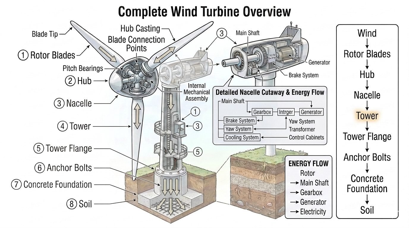
Wind Turbine Tower Structural Design and Foundation Load Paths
In my two decades of heavy structural and piping engineering design, I have evaluated numerous dynamic support systems, but few match the intense fatigue demands placed on modern wind turbine towers. When extreme wind shear meets massive rotating nacelle machinery atop a slender tubular steel shell, the resulting stress distribution requires rigorous engineering.
The entire energy flow mechanism—from the rotor blades to the main shaft, gearbox, and generator—produces dynamic torsional and bending moments that must be safely dissipated. Understanding this continuous load path from the tower flange through the anchor bolt cage into the geogrid foundation is essential for preventing catastrophic structural failure.
Key Engineering Takeaways
- Tower shells experience fluctuating cyclic fatigue from blade shadow and wind turbulence.
- Flange bolting systems require precise pre-tensioning to prevent gapping under extreme bending moments.
- Load paths transfer eccentric nacelle weight directly into the tapered tubular steel wall.
- Foundation anchor cages must transfer massive overturning moments into reinforced subgrade soils.
Structural Engineering and Load Paths in Wind Turbine Towers
As a structural engineer, evaluating the integrity of a wind turbine tower begins at the nacelle bedplate connection. The tower is the primary structural member connecting the nacelle assembly above to the tower flange and foundation below, and is highlighted here as the critical load-carrying path. Loads generated by the rotor blades, hub, and internal nacelle machinery (main shaft, gearbox, generator, all part of the energy flow from Rotor to Main Shaft to Gearbox to Generator to Electricity) travel down through the tower before reaching the tower flange, anchor bolts, and ultimately the concrete foundation and soil beneath.
The tower’s role in this hierarchy is to safely carry the combined weight, bending, and torsional loads from the entire turbine assembly down to the foundation system. To achieve this, designers utilize high-strength structural steels conforming to ASTM A709 or EN 10025 standards, ensuring adequate yield strength and Charpy V-notch toughness under sub-zero operating environments.
Aerodynamic Thrust and Bending Moment Calculations
The primary driver of tower sizing is the maximum thrust force (F_t) exerted by the rotor disc. This force creates an overturning bending moment (M_o) that increases linearly down the tapered shaft toward the base flange. The fundamental thrust equation is expressed as:
Where rho is air density, A is the swept rotor area, V is wind velocity, and Ct is the thrust coefficient. This aerodynamic force acts at the hub height (H), generating a base overturning moment approximated by M_base = Ft × H + M_nacelle, where M_nacelle accounts for the eccentric static mass of the drivetrain.
To resist these extreme moments, tower wall thickness (t) and outer diameter (D) are optimized across multiple ring sections. The section modulus (Z) of a thin-walled circular cross-section governs its bending resistance:
When evaluating stress limits under ASME and DNV-ST-0126 guidelines, combined axial compression and bending stresses must satisfy interaction equations to prevent local shell buckling or yield failure.
Critical Design Warning: Vortex-Induced Vibrations (VIV)
During construction phases before rotor installation, slender tubular towers are highly susceptible to vortex-induced vibrations caused by steady crosswinds. Temporary tuned mass dampers or helical spoiler strakes must be deployed to disrupt vortex shedding and prevent destructive resonant oscillations.
Flange Bolting and Pre-tensioning Protocols
tower sections are joined together using massive internal or external bolted L-flanges. These bolted connections represent structural discontinuities subject to high cyclic tension and compression reversals.
Engineers specify high-strength bolts (typically grade 10.9 or 12.9) tightened to precise elongation thresholds or torque values. Proper pre-load is vital; if bolt tension drops below the separation threshold, cyclic gap opening occurs, leading rapidly to fatigue failure of the bolts.
Foundation Load Transfer Mechanisms
At the base of the tower, the foundation adapter ring or embedded anchor cage distributes loads into a massive reinforced concrete gravity slab or piled cap. The transition zone requires meticulous finite element modeling (FEM) to analyze stress concentrations where the steel shell interfaces with concrete.
Geotechnical parameters—including soil bearing capacity, friction angles, and subgrade modulus—dictate whether a spread footing or deep pile foundation is required to prevent excessive settlement or rocking under operational wind loading.
Structural Advantages
- High bending stiffness-to-weight ratio achieved via optimized tapered tubular geometries.
- Factory-controlled welding and automated nondestructive examination ensure consistent plate quality.
- Modular steel ring fabrication permits efficient transport and rapid onsite erection sequences.
- Smooth external surfaces reduce aerodynamic drag and prevent localized vortex traps.
- Seamless integration with standard flange bolting systems facilitates routine maintenance inspections.
Structural Disadvantages
- Severe susceptibility to high-cycle fatigue cracking at welded longitudinal and circumferential seams.
- Logistical bottlenecking when transporting large-diameter base sections under highway clearance limits.
- Complex corrosion protection requirements inside closed tubular environments requiring active dehumidification.
- High sensitivity to thermal gradients causing differential expansion across thick structural flanges.
- Extensive bolted flange maintenance protocols demanding periodic bolt tension re-verification.
Onshore Utility-Scale Wind Farms
Deploying 100-meter to 160-meter tapered tubular steel towers across flat plains and agricultural corridors. These installations rely on shallow gravity spread footings and standardized internal bolt cages to withstand persistent atmospheric shear profiles.
Offshore Fixed-Bottom Monopiles
Integrating thick-walled transition pieces and large-diameter steel towers in marine environments. The structural design must account for wave slamming forces, marine corrosion protection systems, and multi-directional hydrodynamic fatigue loading.
Complex Mountainous Terrain Installations
Utilizing specialized hybrid towers combining lower precast concrete segments with upper steel sections. This configuration addresses extreme transport weight restrictions while providing the necessary hub height to capture accelerated ridge-line wind flows.
Offshore Floating Wind Platforms
Designing specialized lightweight tubular towers mounted on semi-submersible or tension-leg floating structures. The structural framework must withstand dynamic platform pitch and roll motions while supporting heavy multi-megawatt nacelles.
Wind Turbine Tower Structural Design Parameters
Comprehensive engineering analysis of a wind turbine tower requires strict adherence to standardized material properties, geometric ratios, and environmental load factors. In my professional practice, I rely heavily on ASCE guidelines and ISO standards to establish the baseline parameters for tubular steel and concrete structures. The table below outlines the critical mechanical and dimensional thresholds governing modern utility-scale wind turbine tower design, ensuring structural stability under extreme gust velocities and dynamic fatigue cycles.
Evaluating these parameters prevents premature buckling, bolt relaxation, and excessive deflection at the nacelle yaw ring interface. Each metric directly influences the overall load transfer efficiency from the rotor-nacelle assembly down through the anchor cage and into the reinforced concrete foundation.
| Structural Parameter | Typical Design Value | Governing Standard / Code |
|---|---|---|
| Tower Shell Steel Grade | S355NL / S460QL (ASTM A709 Gr. 50/70) | ASTM A709 / EN 10025 |
| Flange Bolt Preload Ratio | 0.70 to 0.75 of Yield Strength | VDI 2230 |
| Allowable Diameter-to-Thickness (D/t) | Less than 120 (prevents shell buckling) | DNV-ST-0126 |
| Foundation Concrete Class | C45/55 or higher (Min 4000 PSI) | ACI 318 / EN 1992 |
| Anchor Bolt Fatigue Limit | Class 10.9 (Rolled threads) | ISO 898-1 |
Note: Values shown represent baseline engineering practices for onshore utility-scale wind turbine generators operating in IEC Class II wind regimes.
Technical Mapping & Specifications Matrix
Navigating complex wind energy construction projects requires a formalized mapping of structural entities, software verification models, and governing international bodies. The matrix below synthesizes the primary technological subsystems, acronym classifications, and operational parameters that structural engineers use to model tower dynamics and foundation load transfer.
By aligning each structural component with its corresponding verification standard, design teams eliminate ambiguity during the multi-disciplinary review process, ensuring seamless integration between the nacelle assembly, tower sections, and the geotechnical interface.
| Entity / Subsystem | Acronym & Function | Governing Code / Reference |
|---|---|---|
| Rotor Nacelle Assembly | RNA (Generates overturning moments) | IEC 61400-1 |
| Tower Flange Connection | TFC (Transfers tensile and shear loads) | EN 1993-1-8 |
| Foundation Anchor Cage | FAC (Secures tower base to concrete) | AISC Design Guide 1 |
| Finite Element Analysis | FEA (Numerical stress modeling) | ASME V&V 10 |
Reference: Matrix items correspond to standard industrial workflows established for onshore multi-megawatt wind turbine installations.
Wind Turbine Tower Site Verification Checklist
Site verification of wind turbine tower erection and foundation bolting requires meticulous quality control to guarantee long-term structural integrity. Based on my field commissioning experience, overlooking minor torque relaxation or surface preparation flaws can lead to catastrophic fatigue failures under cyclical wind loads.
Use the following structured engineering validation workflow before signing off on tower handover, ensuring strict compliance with ISO and ASME execution standards.
Mandatory Site Inspection Checkpoints
- Flange Surface Cleanliness: Verify mating flange surfaces are entirely free of rust, mill scale, oil, and debris prior to tower section mating, ensuring proper friction coefficient transfer per VDI 2230.
- Anchor Bolt Tensioning: Confirm all foundation anchor bolts are tensioned to specified elongation or torque values using calibrated hydraulic tensioning equipment.
- Grouting Layer Integrity: Inspect the structural grout layer beneath the base flange for void formation, proper curing strength (minimum 50 MPa), and complete load distribution.
- Verticality & Plumbness: Measure tower verticality using laser total stations across orthogonal axes to ensure deviation remains within operational limits (typically less than 1:1000).
- Internal Corrosion Protection: Verify application of touch-up coatings on weld seams, touch-up touchpoints, and dehumidification system operability inside the base section.
- Bolt Relaxation Audit: Schedule and document secondary torque check procedures after the first 72 hours of turbine commissioning and trial rotation.
Completion of this checklist forms an auditable quality record required by project financing entities and insurance underwriters prior to commercial operation date (COD) certification.
Field Case Study: Real-World Application
During the commissioning phase of a 3.4 MW onshore wind farm located in a high-turbulence mountainous ridge, engineering teams detected recurring acoustic emissions and minor bolt tension loss at the mid-tower flanged connection during initial multi-megawatt operational testing.
Problem Analysis
Severe cyclic vortex shedding and complex wind shear interactions induced dynamic fatigue stresses that exceeded the frictional holding capacity of the standard bolted flange assembly.
- Inadequate initial bolt preload verification during rapid winter construction schedules.
- Localized micro-slippage between mating steel flanges under asymmetric bending moments.
- Resonant frequency matching between tower lateral modes and low-frequency rotor harmonic pulses.
- Sub-optimal friction coefficient resulting from residual protective coating on contact surfaces.
Resolved Outcome
Implementing an engineered remediation protocol eliminated joint movement and restored long-term structural fatigue margins.
- Upgraded all high-strength fasteners to Class 10.9 with controlled hydraulic tensioning to 80% yield strength.
- Applied approved friction-increasing zinc-thermal spray coatings to mating flange faces.
- Installed real-time acoustic emission sensors and strain gauges for continuous structural health monitoring.
- Adjusted turbine operational cut-out wind speed thresholds to mitigate extreme thrust loads during storm events.
Engineering Recommendation: For wind farm developments in complex terrain, always enforce strict surface preparation standards and mandate ultrasonic bolt elongation verification to prevent joint degradation.
Frequently Asked Engineering Questions
What are the primary loads transmitted through a wind turbine tower?
- Mass loads from the heavy nacelle assembly, rotor hub, and internal machinery acting vertically.
- Extreme aerodynamic thrust and shear forces generated by wind velocity profiles across the swept area.
- Cyclic fatigue loads induced by rotational blade passage and wind turbulence over multi-year lifespans.
- Torsional moments transmitted during electrical generation and emergency braking events.
How do bolted flange connections maintain structural integrity under cyclic fatigue?
- Preloading bolts significantly beyond standard operational tensile loads to minimize stress amplitude cycles.
- Employing hydraulic tensioning equipment rather than simple torque wrenches to ensure uniform clamping force.
- Implementing regular ultrasonic bolt elongation measurements during scheduled maintenance turnarounds.
- Applying anti-corrosion barrier coatings and protective grease to threads exposed to marine or humid environments.
What differentiates tubular steel towers from hybrid concrete-steel designs?
- Tubular steel towers offer rapid assembly and cost-effectiveness for heights up to 100 meters, constrained by road transport diameter limits.
- Hybrid designs utilize cast-in-place or precast concrete for the lower base section and steel for the upper segment.
- Concrete base sections allow significantly larger base diameters, providing greater stiffness for multi-megawatt turbines exceeding 120-meter hub heights.
- Hybrid solutions reduce overall steel consumption and mitigate fatigue issues in the high-moment lower tower zone.
How does the foundation anchor cage transfer loads to the underlying soil?
- Embedded anchor cages distribute overturning moments from the bottom tower flange directly into heavy reinforced concrete gravity slabs.
- Massive gravity footings rely on dead weight to counteract eccentric bending moments caused by wind shear.
- Piled foundation configurations are deployed in soft soils to transfer axial and lateral loads down to competent bedrock layers.
- Grout layers beneath the base flange eliminate micro-gaps, ensuring uniform pressure distribution across the concrete pedestal surface.
What inspection protocols are required to prevent catastrophic tower fatigue?
- Visual examinations of internal weld seams, access platforms, and bolt tension indicators during annual audits.
- Ultrasonic and magnetic particle testing on high-stress circumferential weld lines near tower base flanges.
- Continuous vibration monitoring using accelerometers to detect anomalous structural resonance or foundation rocking.
- Immediate post-storm structural assessments whenever local wind speeds exceed extreme operational design limits.
As a piping and structural engineering professional overseeing wind energy installations, I advise adhering to strict technical thresholds during design and construction phases. Consider these specific field judgments for your upcoming projects:
- If your site experiences high turbulence intensity and corrosive marine humidity, specify dual-layer epoxy coating systems combined with cathodic protection for all foundation anchor bolts to prevent premature stress corrosion cracking.
- If hub heights exceed 120 meters on soft coastal soils, abandon standard tubular steel profiles in favor of hybrid precast concrete-steel structures to eliminate excessive lateral deflection and natural frequency resonance issues.
- When executing flange bolt tensioning during cold-weather commissioning, always require calibrated hydraulic elongation equipment rather than manual torque multipliers to guarantee uniform pre-load across every fastener in the array.
- During geotechnical site investigations, if bedrock is deeper than 30 meters, mandate a deep-pile friction foundation design coupled with continuous micro-seismic monitoring to safely absorb high overturning moments from the nacelle assembly.
Complete Course on
Piping Engineering
Check Now
Key Features
- 125+ Hours Content
- 500+ Recorded Lectures
- 20+ Years Exp.
- Lifetime Access
Coverage
- Codes & Standards
- Layouts & Design
- Material Eng.
- Stress Analysis
