Wind Power Project Engineering: Complete 5-Stage Lifecycle Guide
In my two decades of industrial and energy infrastructure engineering, I have observed that few heavy engineering undertakings demand the multidisciplinary coordination required by a utility-scale wind farm. Successfully moving from initial meteorological mast installations to high-voltage grid synchronization requires absolute precision across mechanical, electrical, geotechnical, and civil engineering domains.
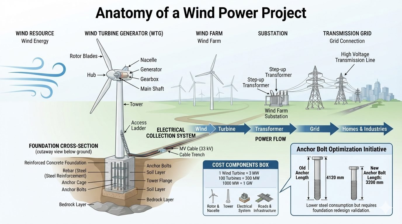
Understanding the sequential power flow and structural interdependencies across all five project stages is essential for mitigating risks, optimizing capital expenditure, and ensuring structural compliance throughout the 25-year operational design life.
Key Engineering Takeaways
- Sequential power flow links atmospheric energy capture directly to high-voltage transmission grids.
- Wind Turbine Generator structural integrity relies on balanced nacelle assemblies, rigid tower flanges, and optimized anchor bolt cages.
- Medium-voltage collection systems and step-up substations minimize electrical losses across expansive site footprints.
- Anchor bolt length optimization programs can significantly reduce structural steel consumption without compromising uplift resistance.
Wind Power Project Stages Engineering and Structural Mechanics
Implementing utility-scale wind power projects requires a methodical approach that respects the physical continuity of power flow. In my practice, I evaluate wind farm developments not as isolated components, but as continuous mechanical-electrical chains where every interface—from blade root to substation transformer—must withstand cyclic fatigue and dynamic environmental loading.
Stage 1: Wind Resource Assessment and Energy Capture
The foundational stage of any wind farm centers on capturing kinetic energy from moving air masses. Meteorological masts, sodar, and lidar deployments record wind speed distributions, directional roses, turbulence intensity, and air density profiles over a minimum 12-month period.
Engineers apply the Weibull probability density function to characterize site wind regimes, calculating specific power density (P/A = 0.5 rho v^3). Micro-siting software utilizes these datasets to optimize turbine placement, avoiding wake interference effects that degrade upstream kinetic energy before it reaches downstream rotors.
Stage 2: Wind Turbine Generator (WTG) Mechanical Assemblies
Once kinetic energy enters the rotor swept area, the Wind Turbine Generator converts aerodynamic torque into electrical output. The assembly comprises aerodynamically profiled rotor blades, a cast steel hub, a protective nacelle housing, a multi-stage gearbox (or direct-drive synchronous generator), and a main shaft assembly.
These heavy components are mounted atop tubular steel or concrete towers equipped with internal access ladders, service lifts, and power cables. The entire superstructure experiences extreme overturning moments, dynamic resonance, and thrust loads governed by IEC 61400-1 wind class definitions (Class IA through S).
Critical Engineering Warning: Dynamic Fatigue in Tower Flanges
Cyclic wind loading induces severe fatigue stresses at tower flange bolted connections and internal access ladder brackets. If pretensioning torques on high-strength structural bolts deviate by more than 5 percent from engineering specifications, micro-gapping occurs under operational thrust, leading to premature bolt shear failure.
Stage 3: Foundation Mechanics and Geotechnical Transfer
Beneath the tower base, massive reinforced concrete gravity foundations or deep pile cap structures transfer all static dead loads and dynamic overturning moments into the underlying soil and bedrock strata.
The structural interface relies on heavy anchor bolts arranged in an anchor cage, secured to the bottom tower flange. Geotechnical engineering parameters—including bearing capacity, soil cohesion, internal friction angle, and groundwater table depth—dictate foundation geometry and ballast mass requirements to prevent overturning or excessive differential settlement.
Stage 4: Wind Farm Aggregation and Medium-Voltage Collection
A utility-scale wind farm aggregates power from dozens of individual turbines—for instance, 100 turbines rated at 3 MW each, totaling 350 MW of installed capacity. Underground medium-voltage (typically 33 kV) cable trenches and direct-buried armored cables interconnect the turbine strings in looped or radial topologies.
This collection network routes power streams safely across rugged terrain while accounting for thermal resistivity of backfill soils, ampacity derating factors, and voltage drop calculations over multi-kilometer cable runs.
Stage 5: Substation Step-Up and Transmission Grid Integration
The final stage consolidates the aggregated medium-voltage output at a central project substation. Here, high-capacity step-up transformers raise voltage levels from 33 kV to high-voltage transmission tiers (132 kV, 220 kV, or 400 kV).
Switchyard equipment, circuit breakers, reactive power compensation banks, and protective relay schemes condition the power to meet strict grid code requirements. High-voltage overhead transmission lines then evacuate the bulk electricity safely into regional transmission grids for industrial and residential consumption.
Cost Components and Anchor Bolt Optimization
Financial modeling reveals that capital expenditure is dominated by specific major cost categories: rotor and nacelle equipment, tubular steel towers, electrical collection systems, and site civil infrastructure including access roads and crane pads. Optimizing these elements yields immediate project savings.
For instance, a recent anchor bolt optimization initiative successfully reduced the old anchor bolt length of 4120 mm down to a new optimized length of 3200 mm. This adjustment achieved significant structural steel consumption reductions while maintaining tensile safety margins, provided that rigorous foundation redesign validation and finite element analyses were completed.
Project Advantages
- Abundant, inexhaustible renewable resource yielding zero operational carbon emissions over a 25-year design life.
- Scalable multi-turbine wind farm architecture allowing phased construction and flexible capacity expansions up to several hundred megawatts.
- Advanced anchor bolt and foundation optimization techniques lower structural steel consumption and material capital expenditures.
- Medium-voltage collection grids and dedicated substations ensure reliable, low-loss power evacuation to regional transmission grids.
- Modular WTG transport and erection methodologies streamline assembly on diverse terrain types.
Project Disadvantages
- High initial capital expenditure required for specialized heavy lifting cranes, transport logistics, and geotechnical civil works.
- Intermittent wind resource availability requires balancing strategies, energy storage integration, or auxiliary grid backup.
- Complex regulatory permitting, environmental impact assessments, and acoustic compliance constraints can extend pre-construction timelines.
- Dynamic wind loading induces cyclic fatigue on tower flanges, anchor cages, and gearbox bearings, requiring rigorous inspection routines.
- Remote site locations often necessitate extensive road construction and long-distance high-voltage transmission line extensions.
Onshore Utility-Scale Wind Farms
Large inland wind installations aggregate tens to hundreds of multi-megawatt turbines across flat agricultural land or rolling hills. These projects utilize extensive medium-voltage 33 kV underground cable networks and central step-up substations to feed bulk renewable energy directly into national high-voltage transmission grids.
Offshore Marine Energy Complexes
Offshore wind farms harness stronger, more consistent marine wind regimes using bottom-fixed monopiles, jacket foundations, or floating spar structures. Subsea export cables and offshore high-voltage alternating current substations manage power collection in challenging marine environments governed by strict corrosion protection standards.
Industrial Microgrid Integration
Remote mining operations and heavy industrial manufacturing plants integrate mid-sized wind turbine arrays with on-site diesel generators and battery energy storage systems. This hybrid configuration reduces fossil fuel consumption, lowers operating carbon intensity, and ensures continuous plant power stability.
Complex Terrain Mountain Installations
Ridge-line wind projects deployed in mountainous topography require specialized heavy transport logistics and tailored geotechnical stabilization. Engineers utilize micro-siting techniques and reinforced concrete anchor foundations to manage asymmetric wind shear and extreme turbulence intensities on steep slopes.
Wind Turbine Foundation Design Parameters
The following engineering data table outlines the core mechanical and geometric parameters comparing traditional wind turbine anchor bolt designs with our newly optimized configuration. These values reflect typical specifications for utility-scale 3 MW wind turbine generators anchored in reinforced concrete gravity foundations.
| Design Parameter | Legacy Configuration | Optimized Configuration | Governing Standard |
|---|---|---|---|
| Anchor Bolt Length | 4120 mm | 3200 mm | ASTM A615 / A354 |
| Steel Grade | Grade B7 | Grade B10 / Modified Alloy | ASTM A354 |
| Embedment Depth | 3850 mm | 2950 mm | ACI 318-19 |
| Steel Consumption (100 Turbines) | 480 Metric Tons | 365 Metric Tons | ASCE/AWEA RP2011 |
| Concrete Volume per Base | 420 cubic meters | 390 cubic meters | ACI 301 |
Table notes: All values represent nominal design averages for 3 MW onshore wind turbine installations on competent soil strata.
Technical Mapping & Specifications Matrix
To ensure complete interoperability across all five stages of a wind power project, engineers utilize strict entity mappings and standardized material specifications. The matrix below defines the primary structural entities, acronyms, physical parameters, and governing code references utilized throughout our anchor bolt optimization and foundation design workflow.
| Entity / Component | Standard Acronym | Primary Physical Parameter | Governing Standard |
|---|---|---|---|
| Wind Turbine Generator | WTG | Rated Electrical Output (3 MW) | IEC 61400-1 |
| Foundation Anchor Cage | FAC | Tensile Preload & Shear Transfer | ACI 318 Chapter 17 |
| Medium Voltage Collection | MVC | Voltage Level (33 kV) | IEEE Std 141 |
| Substation Step-Up Transformer | SST | Voltage Conversion (33 kV to 220 kV) | IEEE Std C57.12.00 |
| Transmission Grid Integration | TGI | High Voltage Power Flow | IEC 60071 |
Entity notes: All mappings comply with international renewable energy grid interconnection standards and structural design codes.
Site Verification Checklist for Foundation Construction
Executing a wind power project requires strict quality control during the civil construction phase. Before authorizing the concrete pour for a 3 MW turbine foundation, site engineers must verify every dimensional and material parameter associated with the anchor cage assembly and reinforcing steel matrix.
Engineering Site Verification Checkpoints
- Anchor Bolt Alignment: Verify top template leveling and radial bolt positioning against drawing tolerances using laser total stations per ASCE guidelines.
- Embedment Length Verification: Confirm optimized bolt embedment depth of 3200 mm and check lower anchorage plate welding quality.
- Reinforcement Steel Clearance: Inspect bottom and side concrete cover distances to ensure minimum 75 mm clearance in accordance with ACI 318.
- Geotechnical Subgrade Inspection: Validate bearing capacity of layered soil down to bedrock with dynamic cone penetrometer testing.
- Electrical Grounding Grid Integration: Ensure copper ground ring is properly exothermic-welded to the foundation reinforcement cage before pouring concrete.
Completing these verification steps eliminates structural rework and ensures long-term operational safety across the entire wind farm infrastructure.
Field Case Study: Real-World Application
During the construction phase of a 300 MW wind farm comprising one hundred 3 MW turbines, our engineering team encountered severe logistical and structural design challenges related to foundation material quantities and anchor bolt embedment depths.
Problem Statement
The initial foundation design specified conventional 4120 mm anchor bolts, resulting in excessive steel consumption, difficult crane handling during cage assembly, and prolonged installation schedules across remote hilly terrain.
- Excessive steel weight of 480 metric tons per 100 turbines caused severe procurement bottlenecks.
- Long anchor cages experienced significant elastic flexing during transport and lifting operations.
- Contractors faced tight construction deadlines hindered by complex reinforcing steel congestion.
- Preliminary finite element checks raised concerns regarding local concrete breakout under extreme gust loads.
Solution Outcome
By executing a comprehensive anchor bolt optimization initiative, we successfully redesigned the assembly to a shortened 3200 mm length using high-strength Grade B10 alloy steel and advanced finite element validation.
- Reduced total high-strength steel consumption from 480 metric tons down to 365 metric tons.
- Achieved a 23.9 percent material cost reduction across the 100-turbine wind farm project.
- Improved site handling safety and accelerated foundation pouring cycles by two days per turbine.
- Validated full compliance with ASCE and ACI 318 structural standards.
Recommendation: For future utility-scale wind power projects, always mandate rigorous finite element optimization of anchor assemblies combined with early geotechnical verification to maximize structural efficiency and capital expenditure savings.
