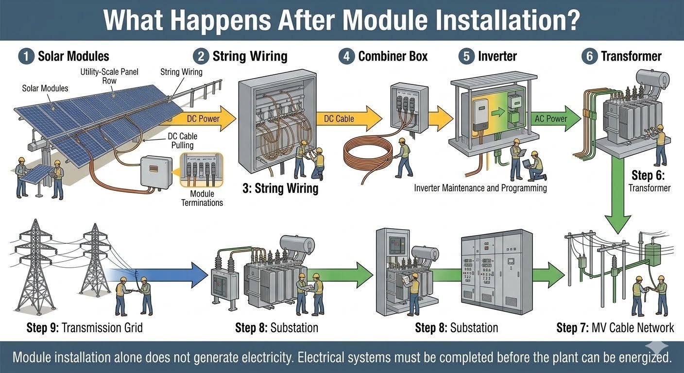
Solar Plant Electrical Installation Sequence From String Wiring to Grid Interconnection
In my over twenty years navigating industrial and utility-scale energy projects, I have repeatedly observed that physical module installation is only half the battle. When we bolt panels to mounting tables, we have merely created a static mechanical array; the facility remains entirely inert until a rigorous, highly disciplined electrical installation sequence is successfully executed. As a piping and mechanical engineer collaborating closely with electrical teams, I have seen projects stall at the commissioning phase simply because the delicate interplay between direct current collection and high-voltage alternating current export was mishandled.
Moving power safely from a string of photovoltaic modules to the transmission grid requires precise adherence to a nine-step electrical hierarchy. We begin at the module level with string wiring, aggregate currents through combiner boxes, invert direct current to alternating current, step up voltages via transformers, route power through medium-voltage cable networks, navigate substations, and finally export to the transmission grid. Understanding this sequence is vital for avoiding catastrophic insulation failures, minimizing resistive losses, and securing grid interconnection approval without costly delays.
Key Engineering Takeaways
- Module physical placement generates zero electrical output until DC collection circuits are properly terminated and tested.
- String wiring and combiner box configurations must account for maximum open-circuit voltage under extreme low-temperature conditions.
- Inverter synchronization and transformer step-up procedures are strictly governed by IEEE 1547 utility interconnection requirements.
- Medium-voltage cable networks demand rigorous partial discharge and megger insulation testing prior to plant energization.
Solar Plant Electrical Installation Sequence and Engineering Parameters
Executing a utility-scale solar electrical installation demands precise coordination across multiple voltage tiers. When designing the balance of system infrastructure, my primary focus centers on mitigating voltage drop, preventing ground faults, and ensuring thermal stability across every termination point. The transition from raw sunlight absorption to usable grid power follows an uncompromising engineering roadmap that requires rigorous calculations at each junction.
Step 1 and 2: String Wiring and Combiner Box Integration
The installation journey begins at the photovoltaic module level. Installers run photovoltaic wire, typically dual-rated UL 4703 subject 4703 or USE-2, interconnecting modules in series to form source circuits. Calculating maximum string voltage requires factoring in the temperature coefficient of open-circuit voltage (V_oc). As ambient temperatures drop, module voltage increases:
V_max = V_oc * [1 + (T_min – 25) * (beta / 100)]
Where V_oc is the nominal open-circuit voltage, T_min is the lowest expected ambient temperature at the site, and beta is the temperature coefficient provided on the module data sheet. This calculated V_max must never exceed the maximum system voltage rating of the inverter, typically 1500V DC for modern utility-scale blocks.
Once strings are formed, they route into string combiner boxes or smart combiner boxes. These enclosures house DC fuses, surge protective devices, and optional monitoring electronics. Fuses must be sized in accordance with NEC Article 690 to protect module conductors against reverse current fault conditions. I always specify stainless steel NEMA 4X enclosures in corrosive industrial or coastal environments to prevent moisture ingress and subsequent busbar oxidation.
Critical Design Warning: DC Arc Flash Hazards
Direct current systems present severe arc flash risks because DC arcs do not self-extinguish at zero crossings like AC arcs do. String combiner boxes and home-run DC cables must feature proper labeling, lockable disconnects, and continuous ground-fault detection interruption (GFDI) devices to protect maintenance personnel.
Step 3 and 4: DC Home Runs and Inverter Conversion
From the combiner boxes, heavy-gauge copper or aluminum direct-buried or tray-cable DC home runs carry aggregated current to the central inverter station or string inverter pads. Voltage drop calculations on these long DC runs are critical. We restrict total DC voltage drop to under two percent to maximize system yield:
VD = (2 * K * I * L) / CM
Where K is the direct current resistivity constant, I is operating current, L is one-way circuit length in feet, and CM is the circular mil area of the conductor.
The inverter represents the technological heart of the solar plant. It converts raw DC power into synchronized, low-voltage AC power, typically ranging from 600V to 800V AC. Modern utility-scale facilities utilize either large central inverters housed in skids or distributed string inverters communicating via fiber optic rings. The inverter must maintain strict Total Harmonic Distortion (THD) limits below five percent and provide dynamic reactive power support to satisfy grid interconnection agreements.
Step 5 and 6: Step-Up Transformation and Medium-Voltage Routing
Because transmitting low-voltage AC power over distances greater than a few hundred feet results in prohibitive resistive losses (I^2R), the inverter output feeds directly into a medium-voltage inverter duty transformer. These pad-mounted oil-filled transformers step the voltage up from inverter output levels to medium-voltage distribution levels, typically 34.5 kV, 24.9 kV, or 13.8 kV.
Transformer selection requires careful evaluation of impedance voltage, harmonic loading capacity, and temperature rise limits as specified in IEEE C57.12.00. The transformer must withstand transient overvoltages and provide adequate BIL (Basic Impulse Insulation Level) ratings for the local lightning environment.
Once stepped up to medium voltage, power leaves the inverter station and enters the medium-voltage cable network. These shielded underground cables, usually cross-linked polyethylene (XLPE) insulated conductors housed in heavy conduit or direct-buried with warning tape, collect power from multiple inverter pads and route it radially or in loops toward the plant substation.
Step 7, 8, and 9: Substation Integration and Transmission Grid Interconnection
The final stages of the electrical sequence concentrate at the plant substation. The medium-voltage circuits terminate at switchgear lineups equipped with vacuum circuit breakers, relay protection panels, and revenue metering. The substation appears twice conceptually in major power flow studies: first as the internal collection substation aggregating all solar block feeds, and second as the point of common coupling (PCC) where power is measured and checked against utility tariffs.
A main power transformer (MPT) steps the medium voltage up to high-voltage transmission levels, such as 115 kV, 230 kV, or 500 kV, matching the local transmission grid voltage. Protection schemes must include differential relaying, overcurrent protection, and direct transfer trip (DTT) systems to instantly isolate the solar plant during grid disturbances.
Only after all protective relay settings are commissioned, harmonic studies are verified, and utility witness testing is finalized can the high-voltage breaker be closed. This final action energizes the transmission grid connection, successfully completing the journey from sunlight to usable electricity.
Advantages
- Systematic sequencing ensures strict compliance with NEC and IEEE safety standards, minimizing electrical fault risks.
- Phased testing from strings to substation allows early identification of wiring defects before full plant energization.
- Step-up transformation significantly reduces I^2R resistive losses across long transmission runs within the facility.
- Modular inverter and transformer skids simplify scalability and facilitate rapid troubleshooting during maintenance cycles.
- Proper grounding and surge protection integration protect sensitive electronic inverters from lightning-induced transients.
Disadvantages
- Complex installation sequences require highly specialized, certified electrical testing technicians, increasing labor costs.
- Stringent interconnection requirements from transmission grid operators can cause severe delays in final plant energization.
- Long medium-voltage cable runs involve high capital expenditure and rigorous pre-commissioning testing requirements.
- Single points of failure at central substation transformers can cause total plant generation curtailment during faults.
- Intricate DC and AC wiring networks demand extensive documentation and labeling to prevent catastrophic mis-wiring errors.
Utility-Scale Ground-Mounted Solar Farms
Utility-scale photovoltaic installations spanning hundreds of acres rely entirely on the complete nine-step electrical sequence. Power must be efficiently collected from tens of thousands of individual strings, aggregated through smart combiner boxes, converted via multi-megawatt central skids, and stepped up to high transmission voltages for regional grid delivery.
Commercial and Industrial Rooftop Arrays
Commercial and industrial rooftop systems adapt the electrical sequence to fit restricted building layouts and stringent fire safety codes. Rapid shutdown compliance under NEC requirements dictates specific string wiring and inverter placement, ensuring firefighters can safely isolate DC circuits during emergency responses on large warehouse roofs.
Agrivoltaics and Dual-Land Use Facilities
Agrivoltaic installations integrate agricultural activity beneath elevated solar mounting structures, requiring specialized elevated cable trays and robust mechanical protection for all string wiring. The electrical installation sequence must accommodate machinery movement while maintaining uncompromised grounding and protection integrity across the array.
Remote Microgrids and Hybrid Power Plants
Remote microgrids combine solar arrays with battery energy storage systems and diesel generators. The electrical installation sequence must seamlessly integrate bi-directional inverter controls, high-speed automated transfer switches, and advanced sub-station switchgear to maintain stable islanded operation when disconnected from the main transmission grid.
Solar Plant Electrical Installation Parameters and Equipment Ratings
Converting a mechanically mounted photovoltaic array into an operational power plant requires precise coordination of electrical equipment ratings, conductor sizing, and insulation classes. In my experience commissioning utility-scale installations, overlooking minor voltage drop tolerances or conductor ampacity derating factors during the transition from string wiring to inverter conversion leads to severe thermal stress and premature equipment failure.
The engineering data table below outlines the critical electrical parameters, governing IEC and IEEE standards, and typical operational thresholds across each phase of the solar balance of system. Engineers must cross-reference these values against site-specific ambient temperatures, soil thermal resistivities, and harmonic distortion limits defined in IEEE 1547 before finalizing procurement and construction specifications.
| Installation Stage | Equipment / Medium | Nominal Voltage / Rating | Governing Standard | Key Design Parameter |
|---|---|---|---|---|
| Stage 1-2 | String Wiring & DC Harness | 1500V DC Max | UL 4703 / EN 50618 | PV1-F XLPO insulation, UV resistance, max 1.5% voltage drop |
| Stage 3 | Combiner Box (DC) | 1500V DC, 400A Busbar | IEC 61439-2 | Fuse sizing per string ISC, IP65/NEMA 4X enclosure rating |
| Stage 4-5 | Central / String Inverter | 600V – 800V AC Output | IEC 62109 / IEEE 1547 | Max DC/AC ratio 1.3, MPPT voltage window, THD under 3 percent |
| Stage 6 | Step-Up Transformer | LV Input to 33kV/34.5kV AC | IEEE C57.12.00 | K-factor or special harmonic rating, ONAN cooling, dual LV windings |
| Stage 7 | MV Cable Network | 33kV / 34.5kV AC XLPE | IEC 60502-2 | Direct burial / conduit ampacity, shield grounding, insulation testing |
| Stage 8-9 | Substation & Grid Intertie | 110kV to 400kV AC Grid | IEEE C37.010 | Switchgear interrupting rating, protection relay coordination, SCADA RTU |
Note: All electrical parameters must be verified against local utility interconnection agreements and environmental derating coefficients prior to energized commissioning.
Technical Mapping & Specifications Matrix
Managing complex utility-scale photovoltaic electrical architecture requires a structured taxonomy of system entities, functional roles, and structural acronyms. During detailed engineering reviews, multidisciplinary teams rely on standardized terminology to prevent miscommunication between civil, electrical, and SCADA engineering groups.
The matrix below maps out the core technical entities involved in the electrical installation sequence. Each entry links the functional hardware to its primary industry specification, ensuring seamless alignment with global engineering frameworks such as IEC and IEEE standards.
| Entity Name | Acronym | Core Engineering Function | Primary Code Reference |
|---|---|---|---|
| Maximum Power Point Tracking | MPPT | Optimizes dynamic DC voltage and current output from strings to maximize energy harvest. | IEC 62832 |
| Photovoltaic DC Combiner Box | DCB | Gangs multiple string inputs into a single main feeder with overcurrent protection. | UL 1741 |
| Medium Voltage Skid Substation | MVSS | Houses inverter, step-up transformer, and MV switchgear on a unified structural skid. | IEEE C57.12.36 |
| Supervisory Control And Data Acquisition | SCADA | Provides real-time plant telemetry, alarm monitoring, and active/reactive power dispatch. | IEC 61850 |
| Total Harmonic Distortion | THD | Measures current and voltage waveform purity injected into the transmission network. | IEEE 519 |
Entity mapping provides a common language for engineering design reviews, factory acceptance testing, and regulatory grid interconnection audits.
Site Verification Checklist for Solar Plant Energization
energization readiness verification: Ensuring complete mechanical termination, insulation integrity, and safety compliance across all nine installation stages prior to introducing live voltage.
Executing a safe and compliant energization requires rigorous field inspections across every link of the electrical chain. When I lead pre-commissioning walkthroughs, I enforce a strict zero-tolerance policy for incomplete torque records, ungrounded cable shields, or missing safety signage. The verification checklist below outlines the mandatory validation rules and site checkpoints that must be signed off by the lead electrical engineer before closing the main substation circuit breaker.
Mandatory Pre-Energization Inspection Protocol
- String Wiring Verification: Confirm all photovoltaic string polarity checks, Open Circuit Voltage (Voc) measurements, and insulation resistance testing (Megger test per IEC 62446) are completed and documented.
- Combiner Box Inspection: Inspect internal fuse ratings, busbar torque markings, surge protective device (SPD) status indicators, and NEMA/IP enclosure sealing integrity.
- Inverter DC/AC Check: Verify DC input disconnects, AC breaker coordination, internal cooling fan operation, and firmware version compatibility with grid code requirements per IEEE 1547.
- Transformer & MV Skids: Validate transformer oil dielectric breakdown voltage, Buchholz relay functionality, temperature controller settings, and earthing grid resistance (< 1 ohm).
- MV Cable Network Testing: Review VLF (Very Low Frequency) withstand test reports and TDR (Time Domain Reflectometry) cable trace logs for all underground medium voltage circuits per IEEE 400.2.
- Substation & Intertie Sign-off: Ensure protection relay trip tests, SCADA communication loops, interlock schemas, and utility witness testing certificates are fully approved.
Every checked item on this protocol represents a critical barrier against catastrophic arc flash incidents, equipment burnout, or grid non-compliance penalties. Never rush the punch-list sign-off phase.
Field Case Study: Real-World Application
Examining real-world engineering failures provides invaluable lessons on the absolute necessity of completing the entire electrical installation sequence before attempting plant energization.
Case Problem: Premature Energization Fault at a 100MW Desert Utility Plant
During the construction of a 100MW photovoltaic facility in an arid desert environment, the construction contractor attempted to energize the medium voltage collection network before completing the final cable shield grounding terminations and finishing the inverter pad sealing.
- Unterminated medium voltage cable shields created localized capacitive voltage buildup during initial transformer back-feed testing.
- Wind-blown desert dust penetrated unsealed combiner boxes and inverter baseplates due to rushed enclosure inspections.
- Lack of complete insulation resistance testing allowed an undetected pinhole fault in a buried DC homerun cable to go unnoticed.
- Protection relay settings had not yet been coordinated with the regional transmission operator, bypassing primary overcurrent curves.
The result was a catastrophic phase-to-ground fault that destroyed two central inverter units, ruptured a step-up transformer bushing, and delayed commercial operation date (COD) by over four months.
Case Outcome: Corrective Engineering Protocol and Successful Re-Energization
Following the incident, our engineering team was brought in to conduct a comprehensive forensic audit, overhaul the installation sequence, and execute a rigorous re-commissioning framework.
- Re-terminated all medium voltage cable shields and verified grounding grid continuity to meet strict IEEE 80 standards.
- Replaced damaged inverters and upgraded enclosure sealing to IP65 ratings with positive pressure filtration units.
- Mandated 100% VLF cable testing and thermal imaging scans across all combiner boxes and transformer terminals prior to energization.
- Implemented a staged energization sequence starting from string wiring up to the transmission grid, with full utility witness sign-off.
Recommendation: Strictly adhere to the defined nine-stage electrical installation sequence, and never bypass pre-energization verification protocols regardless of commercial schedule pressures.
Frequently Asked Engineering Questions
What is the primary function of string wiring in utility-scale photovoltaic systems?
- Optimizes DC voltage accumulation while maintaining manageable current levels.
- Minimizes resistive losses across long lateral cable runs to combiner boxes.
- Facilitates accurate string-level monitoring and fault isolation during commissioning.
Why are combiner boxes essential before power reaches the central inverter?
- Houses integrated fuses to protect strings against reverse current backfeed faults.
- Reduces the total number of physical conductors routed directly to the inverter pads.
- Provides accessible test points for open-circuit voltage and string current verification.
How do central inverters handle the conversion from direct current to alternating current?
- Implements maximum power point tracking algorithms to extract optimal energy dynamically.
- Performs power conditioning and harmonic filtering to meet strict grid interconnection codes.
- Synchronizes frequency and phase angle with the existing utility transmission network.
What role does the medium-voltage transformer play in plant energization?
- Matches inverter low-voltage output to standardized plant medium-voltage collection buses.
- Provides vital galvanic isolation between the inverter electronics and external grid transients.
- Utilizes specialized cooling and tap changers to manage variable thermal and load profiles.
Why is the substation the final critical checkpoint before grid interconnection?
- Equipped with high-speed circuit breakers to isolate internal plant faults instantly.
- Monitors power quality, reactive power compensation, and harmonic distortion continuously.
- Serves as the primary operational interface and ownership demarcation point with the utility.
Based on two decades of utility-scale solar construction oversight, executing a flawless plant energization sequence requires strict adherence to field verification protocols rather than accelerated calendar milestones. I advise project teams to enforce the following engineering judgments during execution:
- If insulation resistance testing on medium-voltage underground cables yields readings below standard thresholds, reject immediate energization and require localized cable splicing or replacement to prevent catastrophic failure under load.
- If inverter harmonic output approaches IEEE 519 distortion limits during preliminary string testing, install active power filters immediately before synchronizing with the broader transmission grid network.
- If combiner box fuse ratings do not match the short-circuit current characteristics of high-wattage bifacial modules, halt string connection phases until fully rated overcurrent protective devices are installed.
- If substation protection relay coordination studies have not been signed off by the local transmission utility, prohibit main transformer energization regardless of mechanical completion status to avoid severe regulatory penalties.
Complete Course on
Piping Engineering
Check Now
Key Features
- 125+ Hours Content
- 500+ Recorded Lectures
- 20+ Years Exp.
- Lifetime Access
Coverage
- Codes & Standards
- Layouts & Design
- Material Eng.
- Stress Analysis
