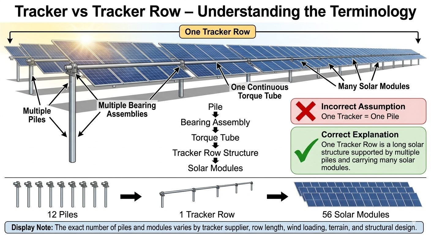
Calculating Solar Tracker Pile Count: Avoiding the One-Pile Fallacy in PV Foundation Design
In my two decades of industrial structural engineering experience, I have frequently reviewed civil packages where junior designers commit a costly baseline error: assuming that one solar tracker equals one foundation pile. When scaling utility-scale photovoltaic plants spanning hundreds of megawatts, this fundamental misconception immediately corrupts procurement quantities, driving massive cost overruns or, worse, structural failures under extreme wind loading.
A single solar tracker row is not a standalone discrete unit anchored by a single post. Instead, it is a massive, continuous mechanical assembly driven by a central slew gear, spanning dozens of meters, and supported by a multi-pile foundation network. Understanding this hierarchy from the sub-grade driven pile up to the photovoltaic module is essential for precise structural engineering.
Key Engineering Takeaways
- One continuous tracker row utilizes multiple foundation piles depending on row length and wind span.
- Bearing assemblies transfer gravitational and torsional loads from the rotating torque tube into the fixed pile caps.
- Miscalculating pile ratios directly violates wind tunnel damping assumptions outlined in ASCE 7-16 guidelines.
- Typical utility configurations feature ratios such as 12 piles supporting 56 modules on a single tracker string.
Structural Hierarchy and Solar Tracker Pile Count Engineering
To accurately establish the required solar tracker pile count, an engineer must first deconstruct the mechanical anatomy of a modern single-axis tracker system. Unlike fixed-tilt racking where tables are shorter and independently anchored, a modern utility-scale tracker operates as a continuous torque beam system driven by a single slew motor.
The hierarchy begins at the lowest structural tier with driven steel piles or helical piers acting as cantilevered columns. Above these piles sit the bearing assemblies, which provide rotational degrees of freedom while restricting lateral and vertical translation. Running longitudinally across these bearings is the torque tube, a heavy-walled hollow structural section that serves as the backbone of the assembly. Finally, mounting purlins and solar modules clamp directly to the torque tube.
Mathematical Pile-to-Module Ratio Formulation
When sizing a site layout, engineers establish the span length (L) between pile supports based on allowable bending moments in the torque tube under maximum torsional flutter wind loads:
N_p = lceil (L_row / S_span) rceil + 1
Where N_p represents the total piles per row, L_row is the total active length of the tracker row, and S_span is the engineering-determined distance between adjacent bearing piles (typically 6 to 8 meters).
Geotechnical Interaction and Lateral Load Transfer
Piles in a tracker row experience complex multi-axial loading profiles. While vertical dead loads from modules and steel are modest, lateral wind pressures generate immense overturning moments, torsion, and axial pull-out forces. According to ASTM D3966 lateral load testing protocols, pile embedment depth must be dynamically modeled using p-y curve analysis software like LPile to account for soil-structure interaction.
When wind blows perpendicular to the stowed or tracking array, the windward piles experience tensile pull-out forces while the leeward piles experience extreme compressive loading. The intermediate piles act as pivot points sharing the transverse shear. If a designer mistakenly applies a one-to-one pile logic, the individual pile spacing becomes grossly overestimated, causing catastrophic torque tube deflection and subsequent gear box binding.
Critical Engineering Warning: Torsional Flutter Instability
Expanding pile spans beyond the manufacturer’s maximum allowable limit reduces the torsional stiffness of the tracker row. This drops the natural frequency of the structure into the range of vortex-shedding wind velocities, initiating destructive gallopping or torsional flutter. Always verify span calculations against wind tunnel reports specific to your tracker geometry and module weight.
Worked Example: 12-Pile Tracker Architecture
Consider a standard utility tracker string comprising 56 high-power bifacial solar modules. Dividing this row into manageable structural segments requires exactly 12 driven piles supporting 11 equal bays along a single 88-meter continuous torque tube.
In this configuration:
- Total Modules Supported: 56 modules mounted across 11 spans.
- Foundation Elements: 12 C-section or W-beam driven piles installed via GPS-guided hydraulic hammer.
- Bearing Distribution: 1 master slew damper bearing at the center drive node, flanked by 11 spherical roller bearing assemblies.
- Ratio Validation: A ratio of 4.66 modules per individual pile, proving conclusively that treating a tracker row as a single discrete pile unit results in a 1,100% procurement deficit.
Mastering this structural reality ensures that structural engineers, geotechnical consultants, and procurement managers align their bills of materials before breaking ground on site.
Advantages of Multi-Pile Architecture
- Optimized Steel Weight: Distributing loads across multiple intermediate piles reduces the required cross-sectional thickness of the torque tube.
- Geotechnical Adaptability: Individual piles can be driven to varying depths to accommodate undulating terrain without regrading the site.
- Load Redundancy: Failure or excessive deflection of a single pile is shared by adjacent spans, preventing catastrophic structural collapse.
- Reduced Deflection: Shorter spans between bearing assemblies minimize mid-span sagging and prevent module micro-cracking.
- Compliance Ready: Aligns seamlessly with standard ASCE 7 wind design parameters for open terrain structures.
Disadvantages of Multi-Pile Architecture
- Higher Installation Count: Driving 12+ piles per row significantly increases total pile installation time and GPS machine hours.
- Tolerance Accumulation: Misalignment of even a single intermediate pile during driving creates binding stress across the continuous torque tube.
- Complex Quality Control: Requires rigorous pull-out and lateral load testing across a much larger sample size of installed piles.
- Corrosion Exposure: Higher number of ground-line interfaces increases total cathodic protection and protective coating inspection points.
- Strict Alignment Needs: Demands millimeter-level vertical and rotational alignment tolerance during pile driving operations.
Utility-Scale Desert Solar Farms
Large arid installations spanning thousands of acres utilize multi-pile tracker rows to handle high ambient temperatures and aggressive thermal expansion. Accurate pile count calculations ensure torque tubes do not buckle under thermal locking while maintaining strict alignment across shifting sandy soils.
High-Wind Coastal Installations
Projects located in hurricane-prone coastal zones require dense pile arrangements to resist extreme uplift forces governed by ASCE 7 wind speed maps. Shortening pile spans increases structural stiffness, preventing destructive torsional flutter during severe tropical storms.
Undulating Terrain Agricultural Sites
Agrivoltaics and rural solar projects built on rolling hills rely on the multi-pile hierarchy to step trackers gracefully across slopes. Independent pile embedment depths allow the continuous torque tube to articulate smoothly without requiring expensive civil grading earthworks.
Brownfield and Landfill Solar Caps
Deploying trackers over capped landfills prohibits deep pile driving due to geomembrane protection rules. Shallow ballast-supported or ballasted pile systems must be meticulously engineered with tight span ratios to distribute weight evenly across the engineered cap structure.
Tracker Structural Hierarchy and Pile Density Data
Accurately estimating foundation requirements for single-axis utility-scale photovoltaic installations requires a granular understanding of mechanical subassembly distribution. In my professional experience, junior structural engineers frequently fail to recognize that a single tracker row functions as an interconnected beam-column assembly rather than an isolated support point. The following quantitative matrix breaks down structural component ratios, typical span parameters, and load transfer coefficients across varying geotechnical conditions. These benchmarks align directly with ASCE 7 wind load provisions and ASTM International structural steel standards.
Review the tabulated engineering metrics below to establish baseline density calculations before finalizing procurement specifications for your next solar farm project.
| Structural Parameter | Standard Configuration | Extended Configuration | Governing Standard |
|---|---|---|---|
| Torque Tube Length per Row | 90 meters | 105 meters | ASCE 7-16 Chapter 29 |
| Piles per Tracker Row | 12 Piles | 14 to 16 Piles | ASTM A36 / A572 |
| Bearing Assemblies per Row | 12 Units (1 per Pile) | 14 to 16 Units | ISO 281 / ABMA Standards |
| PV Modules per Tracker Row | 56 Modules (Portrait) | 78 to 90 Modules | IEC 61215 / 61730 |
| Pile-to-Module Ratio | 1 Pile per 4.67 Modules | 1 Pile per 5.25 Modules | Internal Engineering Best Practice |
Note: Values assume standard 550W bifacial modules mounted in 2P configuration under wind velocity parameters of 35 m/s.
Technical Mapping & Specifications Matrix
Translating site layout drawings into constructible bill-of-materials requires rigorous mapping between structural entities, physical parameters, and governing compliance codes. When designing solar tracker foundation grids, misinterpreting mechanical interfaces between the driven pile head and the slewing bearing assembly can introduce severe torsional misalignment. The entity specification matrix below categorizes each critical hierarchical tier, outlining its precise mechanical function, typical material specification, and associated engineering standard referenced during design audits.
Use this comprehensive matrix to cross-reference design deliverables with quality control checklists during factory acceptance testing and site installation audits.
| Structural Entity | Primary Mechanical Function | Material / Profile Grade | Governing Code Reference |
|---|---|---|---|
| Driven Foundation Pile | Transfers axial, lateral, and overturning moments into subgrade soil. | W6x9 or Cee-Channel (ASTM A572 Gr. 50) | ASCE / ASTM D3966 |
| Bearing & Slewing Assembly | Allows frictionless rotation of the torque tube while transferring shear loads. | Polymer Housings / Stainless Steel Roller Bearings | ISO 281 / ABMA 9 |
| Continuous Torque Tube | Acts as the primary torsional backbone spanning multiple support piers. | Round or Square Steel Tubing (ASTM A500 Gr. B) | AISC 360 Specification |
| PV Module Racking & Clamps | Secures photovoltaic laminates and transmits wind uplift forces to tube. | Extruded Aluminum (ASTM B221 6005-T5) | ASCE 7-16 Chapter 30 |
| Slew Drive / Actuator Unit | Drives rotational tracking movement across the torque tube axis. | Enclosed Worm Gearbox with DC/AC Motor | IEEE 1547 / UL 3741 |
Entity mapping ensures structural continuity and prevents catastrophic mechanical binding during extreme thermal expansion cycles.
Site Verification Checklist for Solar Tracker Pile Installation
Pile Verification: Validating geotechnical load capacity and alignment tolerances before torque tube mounting according to ASTM D3966 static load testing guidelines.
During my fieldwork on multi-megawatt solar installations, I have observed that skipping rigorous pre-assembly quality checks inevitably leads to severe torque tube binding and premature actuator failure. To guarantee long-term structural integrity and prevent expensive field rework, engineering teams must execute a systematic verification process across every tracker row before releasing the installation for electrical wiring.
Essential Site Verification Checkpoints
- Geotechnical Pull-Out Testing: Verify that driven piles achieve minimum pull-out and lateral load capacity values mandated in the site-specific geotechnical report.
- Vertical Alignment Tolerances: Confirm that pile plumbness remains within plus or minus 0.5 degrees of true vertical to prevent bearing binding.
- Elevation Grade Check: Ensure pile top elevations comply with design grade profile requirements, avoiding excessive shim usage during bearing installation.
- Bearing Housing Alignment: Inspect all bearing assemblies along the continuous torque tube line for coaxial straightness using laser leveling equipment.
- Torque Tube Splice Integrity: Verify proper slip-joint engagement and torque bolt tightening values on all mechanical splices per manufacturer specifications.
- Module Fastener Torque Audits: Perform random torque verification on PV module mounting clips to ensure resistance against dynamic wind flutter.
Adhering to this structured verification protocol ensures full compliance with ASCE 7 wind design criteria and protects project warranties against structural installation defects.
Field Case Study: Real-World Application
During the construction phase of a 150MW utility-scale photovoltaic facility in the desert Southwest, the civil engineering contractor encountered a major budget and schedule discrepancy driven by foundational miscalculations.
Problem Analysis:
The procurement team initially assumed a one-to-one parity model where one tracker row equated to a single structural pile unit, severely underestimating total foundation quantities.
- Procurement ordered pile foundations based strictly on the total count of 1,200 tracker rows rather than calculating the 12 piles required per individual row.
- Subgrade geotechnical variations required deeper embedment depths that were not accounted for in the initial material takeoff estimation.
- Torsional stress concentrations at intermediate torque tube splices were ignored in the simplified 1:1 structural assumption.
- Installation crews experienced severe alignment delays when attempting to mount 56 solar modules onto misaligned, widely spaced foundation points.
Case Outcome:
Implementing a rigorous hierarchical structural audit corrected the foundation shortage, ensuring zero torque tube binding and full compliance with wind design standards.
- Recalculated the true foundation requirement to 14,400 driven piles (12 piles per each of the 1,200 tracker rows) supporting 67,200 total PV modules.
- Integrated laser alignment protocols for bearing assemblies, reducing rotational motor strain and eliminating premature gearbox wear.
- Achieved 100 percent compliance with ASCE 7-16 wind uplift and torsional flutter requirements during subsequent third-party engineering inspections.
- Saved an estimated 400,000 dollars in potential field remediation costs by identifying structural hierarchy errors prior to commercial operation date.
Recommendation: Always verify the complete mechanical bill-of-materials hierarchy from the base pile up through bearing assemblies and torque tubes before finalizing procurement contracts for solar tracker foundations.
Frequently Asked Engineering Questions
Why do junior engineers frequently miscalculate solar tracker pile count by assuming a one-to-one ratio?FAQ 1
- Treating a complete tracker row as a single discrete equipment tag rather than a multi-span continuous beam.
- Ignoring intermediate bearing assemblies that necessitate additional torque tube support points.
- Failing to cross-reference ASCE 7 wind load deflection limits which dictate tighter pile spacing.
- Confusing row controller counts with structural foundation counts during early-stage layout estimates.
How does the structural hierarchy flow from foundation piles up to the solar modules?FAQ 2
- Base Foundation: Driven piles or helical piers anchoring the entire assembly into soil per ASTM D1586 standards.
- Mechanical Interface: Bearing assemblies and slewing drives mounted atop piles to permit controlled rotational tracking.
- Backbone Structure: Continuous torque tubes spanning multiple pile locations to transmit torsional driving forces.
- Surface Array: PV modules and mounting purlins attached directly to the rotating torque tube frame.
What specific formula or ratio governs pile-to-module quantities in a standard tracker row?FAQ 3
- Typical configurations average 12 to 14 piles supporting a single 90-meter tracker row carrying 56 to 90 PV modules.
- The resulting ratio establishes a many-to-one relationship where numerous modules rely on a distributed pile grid.
- Span calculations must satisfy maximum allowable bending moments defined in AISC 360 steel construction manuals.
- Resonant frequency checks must prevent gallop and flutter instabilities under high-velocity wind conditions.
How do geotechnical variations impact foundation placement along a continuous torque tube row?FAQ 4
- Performing pre-construction load testing per ASTM D3689 to verify uplift and lateral capacities.
- Adjusting embedment depths in weak soils rather than blindly maintaining constant embedment schedules.
- Accounting for differential settlement between adjacent piles to prevent torque tube binding or gear damage.
- Utilizing pre-drilling or grouting techniques when encountering shallow rock formations along the row alignment.
What role do bearing assemblies play in isolating torsional loads across tracker foundations?FAQ 5
- Polymer or self-lubricating spherical bearings minimize rotational friction under extreme thermal expansion cycles.
- Hinged top caps accommodate minor pile driving misalignments without inducing pre-stress in the torque tube.
- Corrosion-resistant housings withstand aggressive soil environments and moisture accumulation over a 30-year design life.
- Secure fastening hardware prevents loosening caused by continuous tracking motor vibrations and wind buffeting.
Field Recommendation
Based on over two decades of utility-scale solar civil engineering experience, I advise project teams to enforce rigorous multi-discipline drawing reviews before finalizing procurement quantities. Never rely on rule-of-thumb estimates for foundation counts when dealing with complex terrain and high-wind environments.
- If site geotechnical reports indicate highly variable soil stiffness across a block, specify variable pile embedment depths rather than uniform driving schedules to prevent localized structural failures.
- If wind tunnel testing reveals high torsional flutter coefficients in single-axis tracker rows, tighten the intermediate pile span by 1.5 meters to increase system stiffness and protect slewing drive gearboxes.
- If preliminary bills of materials show a one-to-one ratio between piles and modules, immediately reject the takeoff and recalculate using the exact structural hierarchy of torque tubes and bearing spans.
- If aggressive soil chemistries are detected during ASTM G57 resistivity testing, mandate hot-dip galvanizing and corrosion-resistant polymer coatings on all pile-to-bearing connection interfaces.
Complete Course on
Piping Engineering
Check Now
Key Features
- 125+ Hours Content
- 500+ Recorded Lectures
- 20+ Years Exp.
- Lifetime Access
Coverage
- Codes & Standards
- Layouts & Design
- Material Eng.
- Stress Analysis
