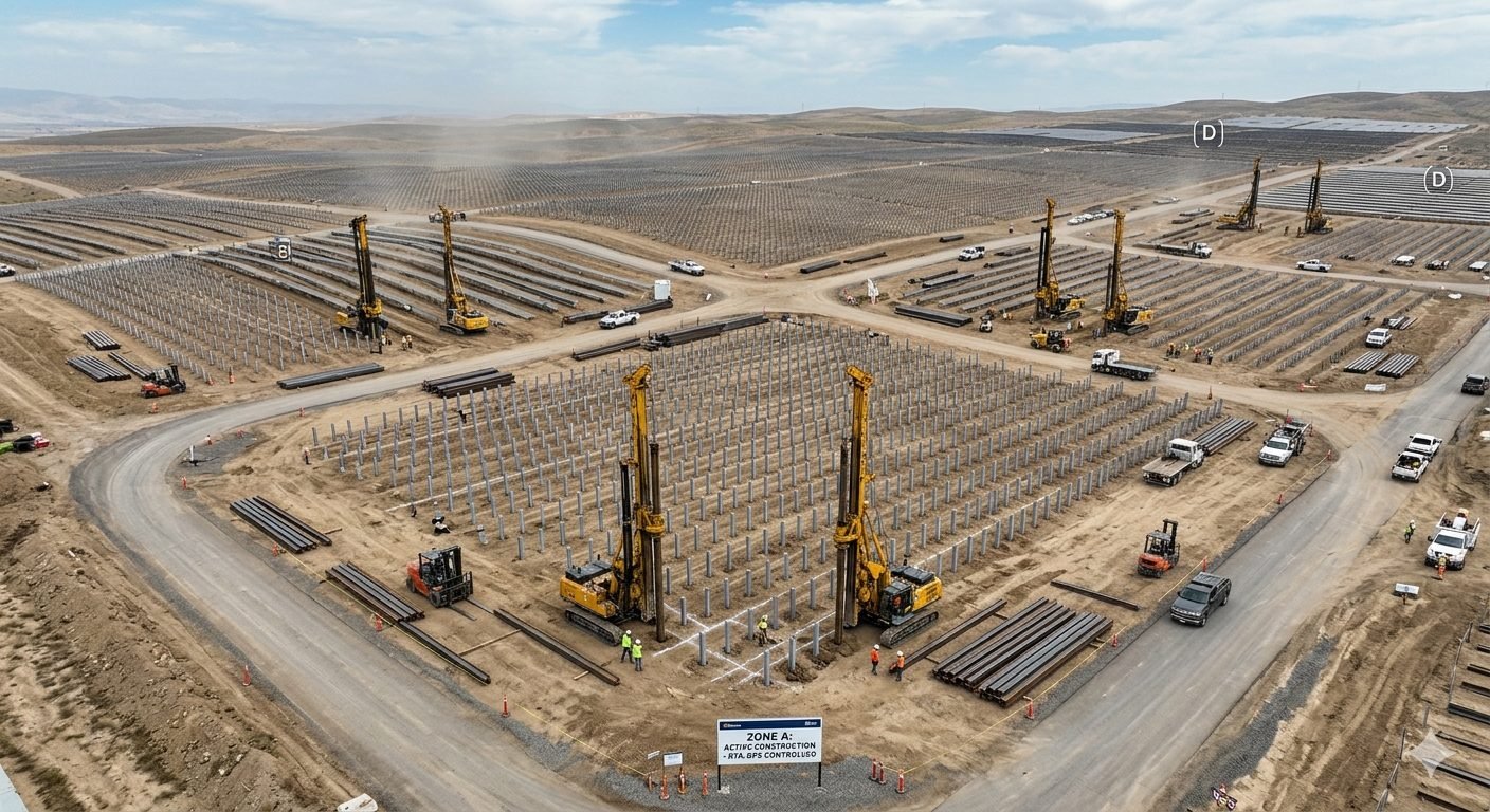
Solar Pile Driving Logistics: Multi-Rig Site Optimization
In my 20+ years of engineering utility-scale energy infrastructure, I have seen many projects stumble not from poor structural design, but from chaotic field execution. When you deploy ten pile-driving rigs across five thousand acres, the site becomes a dynamic factory. Without a rigorous logistical sequence, rigs sit idle waiting for piles, or worse, drive them in the wrong sequence, leading to costly remediation. I have learned that managing these moving parts is just as important as calculating the structural loads themselves.
This guide breaks down the exact engineering and logistical frameworks required to keep multi-rig operations running at peak efficiency. We will examine load calculations, staging strategies, and real-world field scenarios.
- Parallel deployment compresses construction schedules by up to sixty percent.
- Geotechnical verification via ASTM D1143 prevents post-installation settlement.
- Structured staging zones eliminate machine downtime and material handling bottlenecks.
How to Optimize Solar Pile Driving Logistics
Before a single rig tracks onto the site, we must establish a clear geotechnical baseline. I always insist on comprehensive pre-construction testing. Under ASTM D1143, static axial compressive load tests provide the empirical foundation for our design assumptions. These tests determine how the soil-pile interface behaves under extreme vertical loads, which is particularly important for solar trackers subjected to high wind uplift and downward forces.
In my experience, relying solely on standard penetration tests is a recipe for field failures. We must correlate blow counts with actual static load test results across different soil strata. This correlation allows us to map the site into distinct geotechnical zones, each with its own specified pile embedment depth. When multiple rigs operate simultaneously, this zoning ensures that each crew knows the exact driving criteria for their specific sector.
To verify pile capacity during active driving, we utilize dynamic driving formulas. While modern projects often use high-strain dynamic testing, the modified Gates Formula remains a reliable field tool for real-time verification. Let us look at how we calculate the ultimate pile capacity using this method:
Ru = 1.75 * sqrt(E) * log10(10 * N) – 100
In this equation, Ru represents the ultimate pile capacity in kips. E is the manufacturer’s rated hammer energy in foot-pounds. N is the blow count per inch of pile penetration during the final inch of driving.
Let us apply this to a typical utility-scale scenario. Suppose our pile-driving rig utilizes a hammer with a rated energy of 12,000 foot-pounds. During the final stage of driving a wide-flange steel pile, the field engineer records a blow count of 4 blows per inch.
First, we calculate the square root of the hammer energy: sqrt(12000) = 109.54. Next, we calculate the logarithmic component: log10(10 * 4) = log10(40) = 1.602. Now, we substitute these values back into the Gates Formula:
Ru = 1.75 * 109.54 * 1.602 – 100 = 207.1 kips
To find the allowable design capacity, we apply a safety factor of 2.0: Ra = Ru / 2.0 = 103.5 kips. This calculated allowable capacity must exceed the maximum design load calculated during the structural engineering phase. If the blow count drops below 4 blows per inch, the pile has not reached competent load-bearing strata, requiring the rig to drive deeper or necessitating a longer pile.
Managing multiple rigs requires a strict spatial separation strategy. I design site logistics using a hub-and-spoke staging model. Each geographic sector of the solar field acts as an independent production cell. Piles are staged in designated laydown yards immediately adjacent to each sector, minimizing the travel distance for support vehicles.
We must maintain a minimum buffer of two completed rows between active pile-driving rigs and the staging crews. This buffer prevents spatial interference and protects ground crews from heavy machinery hazards. We sequence the rigs to move in a parallel, unidirectional pattern. This prevents rigs from boxing themselves into completed zones, which can disrupt the flow of support vehicles delivering new pile inventory.
Soil moisture levels significantly impact driving resistance and ultimate capacity. During wet seasons, cohesive soils experience a temporary loss of shear strength, leading to deceptively low blow counts. Conversely, dry, compacted clay can cause premature refusal. Engineers must adjust driving criteria based on seasonal geotechnical reports to ensure long-term stability.
We must also account for lateral load resistance. Solar trackers experience massive lateral forces from wind shear. While ASTM D1143 focuses on axial loads, lateral load testing under ASTM D3966 is equally important. The logistics plan must schedule these lateral tests early in the sequence to validate the pile’s lateral deflection limits before mass production driving begins.
Evaluating Solar Pile Driving Logistics Strategies
- Schedule Compression: Deploying multiple rigs simultaneously reduces the overall civil works timeline by up to sixty percent. This rapid progress allows downstream mechanical and electrical installation crews to begin tracker assembly much earlier in the project lifecycle.
- Resource Optimization: Specialized operators focus entirely on driving piles, while dedicated support teams handle material staging and layout marking. This division of labor maximizes the efficiency of each labor hour and reduces operational downtime.
- Geotechnical Adaptability: Rigs can be reassigned dynamically to different sectors if localized soil anomalies or shallow bedrock are encountered. This flexibility prevents site-wide work stoppages while engineering teams resolve localized issues.
- Equipment Redundancy: If one pile-driving rig experiences mechanical failure, other rigs continue working across their respective sectors. This distributed risk minimizes the impact of equipment downtime on the critical path schedule.
- High Congestion Risk: Coordinating multiple heavy machines, support vehicles, and delivery trucks in active sectors increases safety hazards. Without strict traffic management, site roads quickly become congested, slowing down material delivery.
- Increased Quality Control Burden: Managing multiple active driving zones requires a larger team of field inspectors. Each inspector must verify embedment depths, plumbness, and blow counts in real time to prevent installation errors.
- Complex Material Staging: Delivering thousands of piles to multiple active zones simultaneously requires precise inventory tracking. Any breakdown in the supply chain can leave expensive rigs sitting idle, driving up overhead costs.
- Higher Mobilization Costs: Transporting and maintaining multiple heavy pile-driving rigs increases initial project expenditures. The project must support higher fuel consumption, maintenance infrastructure, and operator transport logistics.
Real-World Applications
Optimizing Rig Mechanics: Aligning hydraulic hammer energy with subsurface soil density ensures maximum pile installation speed without structural buckling.
Managing multi-rig operations across a 500-megawatt solar facility requires matching the mechanical strike energy of hydraulic pile drivers to localized geotechnical conditions. In my experience across expansive desert and agricultural sites, deploying identical impact hammers without evaluating variations in Standard Penetration Test (SPT) N-values causes premature equipment wear or structural distortion of steel W-shapes.
The table below outlines production metrics, hammer energy specifications, and refusal criteria derived from real-world utility-scale installations. Adhering to these calibrated operational boundaries prevents foundation over-driving and maintains site velocity under ASTM D1143 static axial compressive load testing standards.
| Subsurface Profile | Hammer Energy Range | Target Embedment | Average Daily Output | Refusal Threshold |
|---|---|---|---|---|
| Loose Sand & Silty Clay (SPT N < 10) | 1.2 kJ – 2.5 kJ | 2.5 m – 3.2 m | 220 – 280 piles / rig | > 10 blows / 100 mm |
| Dense Sand & Stiff Clay (SPT N 10–30) | 2.5 kJ – 4.5 kJ | 2.8 m – 3.8 m | 160 – 210 piles / rig | > 15 blows / 100 mm |
| Very Dense Gravel & Cobbles (SPT N 30–50) | 4.5 kJ – 7.0 kJ | 3.0 m – 4.2 m | 90 – 130 piles / rig | > 20 blows / 100 mm |
| Caliche Layer / Shallow Bedrock (SPT N > 50) | Pre-Drill + 4.5 kJ Hammer | 1.8 m – 2.5 m | 60 – 85 piles / rig | > 25 blows / 100 mm |
Note: Production rates assume an active 10-hour shift per rig with dedicated material support units and pre-staged pile inventory inside designated sector buffers.
Achieving reliable solar pile driving logistics requires strict control over physical parameters, mechanical tolerances, and load test compliance metrics. When managing multiple rig crews operating simultaneously, clear parameter boundaries prevent structural out-of-tolerance errors and keep logistics pipelines functioning smoothly.
The matrix below maps critical structural entities, design boundaries, and engineering standards governing civil foundation deployment on utility-scale solar construction projects.
| System Entity | Symbol / Abbr. | Governing Standard | Operational Limit | Logistical Impact |
|---|---|---|---|---|
| Static Axial Compressive Load | P_ult | ASTM D1143 | 1.5x Design Load | Validates pile embedment depth prior to releasing full tracker row installation. |
| Static Axial Tensile (Uplift) Load | P_up | ASTM D3689 | 1.5x Uplift Load | Determines minimum pile length needed to resist wind overturn forces across sectors. |
| High-Strain Dynamic Testing | PDA | ASTM D4945 | 2% Minimum Total Piles | Provides real-time capacity feedback to adjust rig hammer drop heights immediately. |
| Pile Head Elevation Tolerance | Tol_z | IBC 2021 Ch. 18 | ± 12.5 mm (0.5 in) | Out-of-tolerance heads require secondary trimming or post-extensions, slowing progress. |
| Horizontal Alignment Offset | Tol_xy | ASCE 7-22 / Site Spec | ± 25 mm (1.0 in) | Excessive drift forces structural torque tube binding during mechanical assembly. |
Field Quality Execution: Systematically clearing sector preconditions guarantees continuous production while maintaining full foundation load compliance.
To maintain rapid site progress on large multi-rig projects, civil superintendents and quality managers must execute strict field checks before, during, and after driving each sector grid. Failing to verify surveyor control points or skipping dynamic testing protocols creates rework loops that halt following mechanical tracker crews.
Use this operational checklist on site to verify logistics pathways, pile delivery staging, and foundation testing procedures across every active sector.
Verify GPS survey pin accuracy within ±5 mm. Confirm geotechnical borings match current sector boundaries before rig placement.
Ensure a 48-hour buffer of structural steel piles is unladen and staged along sector access corridors to eliminate crane waiting times.
Inspect hydraulic energy settings on each driver to match target pile resistance profiles without exceeding steel yield limits.
Execute static compressive testing per ASTM D1143 and dynamic analysis per ASTM D4945 on designated test piles before mass production.
Perform real-time laser check on driven piles. Confirm vertical plumbness is within 1.5% slope and head elevation is within ±12.5 mm.
Document refusal locations exceeding blow limits. Transition rig crews to pre-drill augering setups immediately to avoid grid stoppages.
Field Case Study: Real-World Application
Managing simultaneous multi-rig operations demands rigorous traffic control and continuous geotechnical coordination. On a 450-MW solar installation in West Texas, mismanaged field logistics initially resulted in severe site congestion, idle rig time, and high refusal rates.
Initial Operational Breakdown
Six hydraulic driving rigs were deployed simultaneously without designated staging buffers, resulting in severe supply bottlenecks and structural refusal errors.
- Flatbed haulers blocked primary access roads, causing an average of 2.5 hours of idle rig time daily.
- Unmapped dense caliche strata caused pile head buckling on 8% of installed steel profiles.
- Rigs entered active grid rows before static load testing under ASTM D1143 was finalized, forcing partial re-driving.
- Daily pile installation rates fell to 85 piles per rig, far below the planned 180-pile daily baseline.
Logistical Correction & Results
Implementing a pin-point sector routing strategy combined with dedicated pre-drill auger rigs restored site velocity and eliminated vehicle interference.
- Established localized 48-hour material staging buffers in each sector, clearing central access roads for continuous support traffic.
- Integrated two pre-drilling auger units ahead of driving rigs in high-caliche sectors, eliminating structural pile head damage.
- Accelerated pre-production testing using dynamic pile analysis per ASTM D4945 to confirm embedment targets 72 hours early.
- Increased output to 215 piles per rig daily, completing overall project foundation driving 14 days ahead of the revised baseline schedule.
My takeaway from this facility deployment is straightforward: never treat multi-rig driving as a simple fleet exercise. Success depends on establishing clear geographic boundaries, decoupling material deliveries from active driving lanes, and establishing verified load test baselines before driving mass production piles.
Frequently Asked Engineering Questions
How do you manage pile-driving rig interference on large sites?
- Establish non-overlapping work zones defined by clear geographic boundaries.
- Implement a centralized traffic management plan for support vehicles and pile delivery.
- Use real-time GPS tracking to monitor rig progress and adjust sector boundaries dynamically.
- Designate specific haul routes that avoid active driving zones to maintain continuous material flow.
What is the role of ASTM D1143 in pile testing?
- Validate the geotechnical assumptions made during the initial site investigation phase.
- Determine the ultimate load-bearing capacity of the driven piles under field conditions.
- Ensure compliance with project-specific structural requirements for solar tracker foundations.
- Calibrate driving criteria for production rigs based on observed soil resistance data.
How should pile inventory be staged for maximum efficiency?
- Distribute pile bundles across multiple satellite yards to reduce travel time for rigs.
- Organize inventory by length and specification to prevent sorting delays at the rig.
- Maintain clear access paths for heavy-duty delivery trucks to reach staging areas.
- Use inventory management software to track consumption rates and trigger replenishment orders.
What are the primary risks of parallel rig deployment?
- Increased risk of vehicle collisions due to high traffic density in work zones.
- Potential for inconsistent pile quality if rig operators are not calibrated uniformly.
- Logistical strain on support teams trying to service multiple rigs simultaneously.
- Difficulty in maintaining site-wide quality control documentation across disparate work sectors.
How do you ensure consistent pile driving quality?
- Implement daily calibration checks for all pile-driving hammers and sensors.
- Require operators to record blow counts and penetration depths for every single pile.
- Conduct regular spot-checks for verticality using digital inclinometers or laser levels.
- Establish a clear non-conformance reporting process to address piles that fail to meet depth or resistance requirements.
Complete Course on
Piping Engineering
Check Now
Key Features
- 125+ Hours Content
- 500+ Recorded Lectures
- 20+ Years Exp.
- Lifetime Access
Coverage
- Codes & Standards
- Layouts & Design
- Material Eng.
- Stress Analysis
