Mastering Solar Pile Foundation and Connection Design
In my two decades of experience within the industrial and renewable energy sectors, I have observed that the integrity of a utility-scale solar array rests entirely on the foundation. A solar pile foundation is not merely a steel post driven into the earth; it is a precision-engineered structural member that must withstand decades of wind-induced uplift, lateral soil pressure, and thermal expansion cycles.
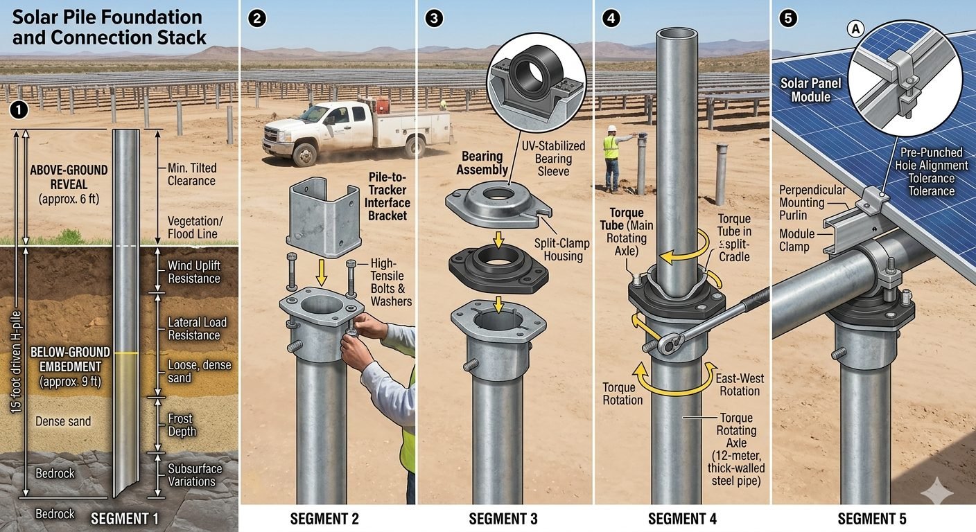
When we analyze the connection stack, we are looking at a complex interface where geotechnical stability meets mechanical rotation. Whether dealing with dense sand or rocky substrates, the interaction between the pile embedment and the torque tube assembly determines the long-term performance of the tracker system. In this guide, I will break down the five critical segments that define these installations, ensuring your designs meet both structural codes and site-specific installation tolerances.
Key Engineering Takeaways
- Embedment depth must account for soil friction and lateral load resistance.
- Bearing assemblies require UV-stabilized materials to prevent premature mechanical failure.
- Torque tube wall thickness is critical for mitigating torsional deflection under high wind.
- Installation tolerances for module clamps must accommodate thermal expansion and site-leveling variations.
Structural Analysis of Solar Pile Foundation Systems
The design of a solar pile foundation begins with the geotechnical report. In my experience, the most common failure mode is not the steel itself, but the soil-pile interaction. We calculate the required embedment depth by evaluating the skin friction of the soil strata. For a typical 8-12 foot embedment, we utilize the alpha method for cohesive soils or the beta method for granular soils to determine the ultimate uplift capacity.
Once the pile is secured, the interface bracket serves as the critical transition point. This component must be designed to handle the moment loads transferred from the tracker. We typically specify high-tensile bolts (ASTM A325 or equivalent) with locking washers to prevent vibration-induced loosening. The bearing assembly, which follows, is the heart of the tracker’s rotation. I prioritize UV-stabilized high-density polyethylene (HDPE) or specialized bronze bushings to ensure the bearing sleeve maintains its tolerance despite constant exposure to solar radiation and thermal cycling.
The torque tube, often a 12mm thick-wall steel pipe, acts as the primary structural spine. Its design is governed by torsional stiffness requirements. We calculate the maximum allowable twist angle to prevent panel damage during high-wind events. The L-foot cradle must be precisely aligned; even a 2-degree deviation in the cradle orientation can induce significant stress on the bearing assembly, leading to premature wear. Finally, the module clamp installation must account for the thermal expansion coefficient of the aluminum frames. If the clamp is too tight, the frame will buckle; if too loose, the module may experience flutter during wind gusts.
To ensure compliance, I always reference the ASCE 7-22 wind load provisions. When calculating the lateral load on the pile, we must consider the projected area of the panels at their maximum tilt angle. The resulting force is applied at the center of pressure, creating a bending moment at the ground line that the pile must resist through its section modulus and the passive resistance of the surrounding soil.
Advantages
- Rapid installation via hydraulic pile drivers.
- Minimal site disturbance compared to concrete footings.
- High load-bearing capacity in dense soil profiles.
- Modular design allows for easy component replacement.
- Excellent resistance to frost heave when properly embedded.
Disadvantages
- Susceptible to corrosion in high-salinity or acidic soils.
- Requires specialized equipment for rocky terrain.
- High sensitivity to installation verticality tolerances.
- Potential for vibration-induced loosening of hardware.
- Limited lateral resistance in loose, saturated soils.
Utility-Scale Desert Arrays
In arid, sandy environments, the pile foundation excels by utilizing deep embedment to bypass loose surface sands. The design focuses on maximizing skin friction to resist wind uplift, which is the primary design driver in open, flat desert landscapes.Agricultural Dual-Use Sites
For agrivoltaic projects, the pile foundation is preferred due to its small footprint, which allows for continued land cultivation beneath the panels. The elevated reveal height is specifically engineered to provide clearance for farm machinery and crop growth.Brownfield Redevelopment
When installing on capped landfills or reclaimed industrial sites, pile foundations are essential because they avoid deep excavation that could compromise site liners. The design relies on shallow, high-density pile grids to distribute the structural load evenly.In my two decades of structural design, I have observed that the integrity of a solar pile foundation relies heavily on the precise calculation of lateral and uplift forces. Engineers must evaluate the soil-structure interaction, specifically focusing on the ASCE 7 standards for wind load distribution across the tracker array. The following table outlines the critical design thresholds for standard steel pile sections used in utility-scale solar projects.
| Load Category | Design Standard | Typical Value Range |
|---|---|---|
| Lateral Wind Load | ASCE 7-22 | 15 to 35 psf |
| Uplift Resistance | ASTM D3689 | 10 to 50 kips |
| Embedment Depth | Geotechnical Report | 8 to 12 feet |
| Torque Tube Deflection | AISC 360 | L/180 to L/240 |
These values represent baseline expectations for typical soil profiles. When working with expansive clays or loose, saturated sands, I always mandate a site-specific pull test to validate the friction coefficients used in the initial structural model.
Managing the complexity of a solar pile foundation requires a clear understanding of the interconnected components. Each segment, from the deep-seated pile to the module clamp, must adhere to specific material specifications to ensure a 25-year operational life. This matrix maps the physical components to their primary structural functions and relevant industry standards.
| Component | Material/Standard | Primary Function |
|---|---|---|
| Foundation Pile | ASTM A572 | Load transfer to soil |
| Bearing Sleeve | UV-Stabilized HDPE | Friction reduction/Rotation |
| Torque Tube | AISC 360 | Structural axle/Rotation |
| Module Clamp | 6061-T6 Aluminum | Panel securement |
By standardizing these entities, we minimize the risk of galvanic corrosion and mechanical fatigue. My experience shows that using mismatched materials at the interface points is the most common cause of premature system failure in high-wind environments.
Verification of the solar pile foundation is the most critical phase of the construction lifecycle. Before the torque tube installation begins, I require a rigorous inspection of the pile reveal and alignment. Any deviation in the verticality of the pile will propagate through the entire tracker system, causing binding in the bearing assemblies and excessive stress on the drive motor.
- 01. Verify pile verticality within 0.5 degrees using a calibrated digital inclinometer.
- 02. Confirm embedment depth meets the geotechnical report requirements for the specific soil zone.
- 03. Inspect the pile-to-tracker bracket for proper torque application on all high-tensile hardware.
- 04. Check the bearing sleeve for signs of deformation or improper seating within the split-clamp housing.
- 05. Validate torque tube alignment across the entire row to ensure smooth east-west rotation.
- 06. Ensure all module clamps are tightened to the manufacturer-specified torque to prevent panel slippage.
These checkpoints are not merely suggestions; they are the foundation of a reliable structural design. In my experience, failing to verify the pile-to-tracker interface before mounting the panels leads to costly rework and potential long-term structural degradation. Always document these checks with photographic evidence and signed inspection logs to satisfy IEEE quality standards.
Problem: Excessive Bearing Wear in High-Wind Zone
A utility-scale project in a high-wind region experienced premature failure of the bearing assemblies within the first six months of operation.
- Misalignment of the torque tube caused uneven loading on the bearing sleeves.
- Inadequate UV protection on the initial bearing material led to embrittlement.
- High-frequency vibrations from wind gusts caused the split-clamp housing to loosen.
- Lack of proper lubrication at the interface increased rotational friction.
Outcome: Optimized Structural Integrity
We implemented a comprehensive remediation strategy that restored the system to full operational capacity.
- Replaced all bearing sleeves with high-density, UV-stabilized HDPE components.
- Installed secondary locking washers on all high-tensile hardware to prevent vibration-induced loosening.
- Performed a full row-by-row realignment of the torque tubes to ensure concentric rotation.
- Established a quarterly inspection schedule for all critical connection points.
My recommendation for future projects is to prioritize the quality of the bearing assembly and the precision of the initial pile installation. Investing in higher-grade materials during the construction phase significantly reduces the total cost of ownership over the project’s lifespan.
Frequently Asked Engineering Questions
How is the embedment depth for a solar pile foundation determined?
- Soil shear strength and density profiles.
- Wind uplift forces acting on the tracker array.
- Frictional resistance along the pile surface area.
- Depth to refusal or bedrock contact points.
What are the primary structural requirements for the torque tube assembly?
- Wall thickness specifications, typically 12mm for structural rigidity.
- Material yield strength to prevent permanent deformation under load.
- Alignment precision within the L-foot cradle to ensure smooth rotation.
- Corrosion resistance coatings for long-term outdoor exposure.
Why is the pile-to-tracker interface bracket critical for system longevity?
- Effective distribution of vertical and lateral loads.
- Prevention of hardware loosening due to vibration.
- Maintenance of structural tolerances during thermal expansion.
- Compliance with manufacturer torque specifications for high-tensile fasteners.
How do bearing assemblies protect the internal tracker components?
- Reducing friction during east-west tracking movements.
- Sealing internal components against moisture and dust ingress.
- Providing a stable housing for the rotating torque tube.
- Extending the service life of the mechanical drive system.
What tolerances must be managed during solar module installation?
- Perpendicular mounting alignment to avoid frame warping.
- Pre-punched hole alignment to prevent fastener binding.
- Accounting for thermal expansion gaps between modules.
- Ensuring uniform clamp pressure to protect glass integrity.
Complete Course on
Piping Engineering
Check Now
Key Features
- 125+ Hours Content
- 500+ Recorded Lectures
- 20+ Years Exp.
- Lifetime Access
Coverage
- Codes & Standards
- Layouts & Design
- Material Eng.
- Stress Analysis
