Optimizing Utility-Scale Solar Pile Foundation Design for Stability
In my two decades of experience across industrial infrastructure, I have observed that the success of a utility-scale solar project often hinges on the invisible engineering beneath the panels. A solar pile foundation is not merely a post in the ground; it is a precision-engineered interface between high-velocity wind loads and the geotechnical capacity of the site.
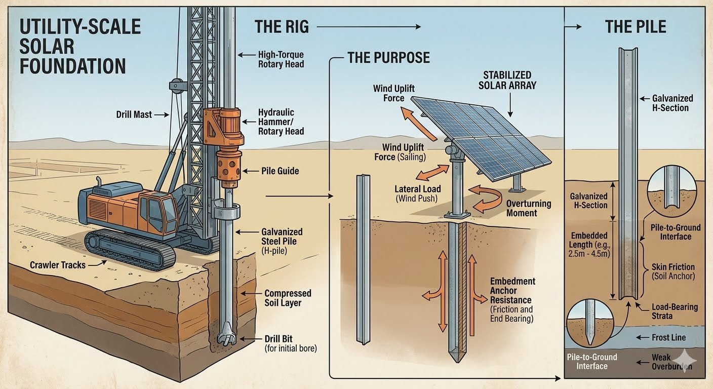
When we deploy a crawler-tracked drilling rig to bore through compressed soil, we are preparing the path for an H-pile that must withstand decades of cyclic loading. Understanding the interaction between the steel section and the surrounding soil matrix is the difference between a resilient asset and a structural failure during a storm event.
Key Engineering Takeaways
- Master the calculation of skin friction versus end-bearing capacity for H-sections.
- Identify the critical overturning zone within the top 1.5 meters of soil.
- Apply ASCE 7 wind load standards to determine uplift and lateral push.
- Optimize embedment depths between 2.5 and 4.5 meters based on site-specific geotechnical reports.
Technical Analysis of Solar Pile Foundations
Solar pile foundations: Structural geotechnical systems designed to resist combined axial, lateral, and moment loads by leveraging soil shear strength and pile section modulus.
Designing a robust foundation requires a deep dive into the mechanics of the H-pile. The primary challenge is the lateral load generated by wind hitting the solar tracker surface. This force creates a significant overturning moment at the ground line. In my experience, the soil resistance in the top 1.5 meters is often insufficient due to surface disturbance and moisture variation, making this the critical zone for lateral stability.
Calculating Soil-Pile Interaction
To calculate the required embedment, we must evaluate the ultimate lateral resistance using the p-y curve method. The lateral capacity is governed by the soil’s modulus of subgrade reaction. For a typical H-pile, the resistance is calculated as:
R_lat = (K_h * y * D) * L_eff
Where K_h is the horizontal subgrade modulus, y is the lateral deflection, D is the pile width, and L_eff is the effective length. We must ensure that the deflection at the ground surface does not exceed the serviceability limit states defined by the tracker manufacturer, typically 10 to 25 millimeters.
Field Warning: The Frost Line Factor
Never terminate an H-pile above the local frost line. Frost heave can exert significant upward force on the pile, potentially compromising the skin friction bond and leading to structural settlement or misalignment of the tracker array. Always verify the local frost depth per regional building codes.
Uplift and Skin Friction Mechanics
Wind uplift is the most common failure mode for solar trackers. The pile resists this through the summation of skin friction along the embedded length. The ultimate uplift capacity is defined by:
Q_u = Σ (f_s * A_s)
Here, f_s represents the unit skin friction, which is a function of the effective overburden pressure and the soil-pile interface friction angle. For galvanized steel, we typically apply a reduction factor to the soil-steel interface friction compared to concrete-soil interfaces. In cohesive soils, we utilize the alpha method, while in granular soils, we rely on the beta method to determine the skin friction coefficient.
The drilling rig’s role is to ensure the hole diameter is optimized. If the hole is too large, the backfill material may not achieve the required compaction, leading to a loss of lateral stiffness. We aim for a tight fit, often using a drill bit diameter only slightly larger than the diagonal of the H-pile section to minimize the annular space requiring grout or native soil backfill.
Foundation performance metrics: A comparative assessment of H-pile systems regarding installation speed, structural reliability, and geotechnical adaptability in utility-scale solar environments.
Advantages
- High lateral load resistance due to the H-section geometry.
- Rapid installation cycles using automated crawler-tracked rigs.
- Excellent performance in dense or rocky soil strata.
- Galvanized coating provides long-term corrosion resistance.
- Predictable load-bearing capacity via standard geotechnical testing.
Disadvantages
- Requires specialized drilling equipment for hard soil.
- Susceptible to frost heave if not embedded deep enough.
- Higher material costs compared to simple driven posts.
- Requires precise alignment to ensure tracker tracking accuracy.
- Potential for soil disturbance during the drilling process.
Utility-scale deployment: Strategic implementation of H-pile foundations across diverse environmental conditions to ensure structural integrity for large-scale photovoltaic arrays.
High-Wind Coastal Solar Farms
In coastal regions, wind uplift is the dominant design force. We utilize deeper H-pile embedment to maximize skin friction, ensuring the tracker structure remains anchored during extreme weather events while resisting the corrosive salt-air environment through heavy-duty galvanization.
Rocky Terrain Utility Sites
When sites feature shallow bedrock or dense gravel, traditional pile driving is impossible. The crawler-tracked drilling rig allows us to pre-bore through the hard layer, ensuring the H-pile reaches the required depth for end-bearing capacity without damaging the structural integrity of the steel.
Expansive Clay Soil Environments
Expansive soils pose a risk of pile movement due to moisture-induced volume changes. By using a drilled and backfilled H-pile, we can control the soil-pile interface properties, effectively isolating the pile from the upper active soil zone and anchoring it into the stable, deeper strata.
Designing a utility-scale solar pile foundation requires precise calibration of geotechnical variables against structural demand. The following table outlines the standard design parameters I utilize when evaluating H-pile performance under combined wind and gravity loads. These values are derived from ASCE 7 wind load standards and ASTM D1143 testing protocols for deep foundations.
Engineers must account for the soil-structure interaction, specifically the modulus of subgrade reaction, which dictates the lateral deflection of the H-pile near the surface. By cross-referencing these parameters with site-specific borehole logs, we ensure the pile maintains structural integrity during extreme weather events.
| Parameter | Typical Range | Standard Reference |
|---|---|---|
| Embedment Depth | 2.5m to 4.5m | ASCE 20 |
| Skin Friction Coefficient | 0.3 to 0.7 | ASTM D3689 |
| Lateral Deflection Limit | 10mm to 25mm | IBC 1810 |
| Steel Yield Strength | 250 to 350 MPa | ASTM A36 |
The following matrix maps the critical engineering entities involved in solar pile foundation design. Understanding the relationship between the mechanical rig, the soil medium, and the structural steel is fundamental to achieving a stable tracker array. I categorize these entities based on their role in load path distribution and geotechnical resistance.
By mapping these components, we can identify potential failure modes early in the design phase. This matrix serves as a quick-reference guide for site engineers to ensure that the H-pile specifications align with the site’s specific soil classification and environmental loading requirements.
| Entity | Function | Code/Standard |
|---|---|---|
| Crawler Rig | Precision pile installation | OSHA 1926 |
| H-Pile Section | Load bearing and uplift | ASTM A572 |
| Soil Stratum | Skin friction resistance | ASTM D2487 |
| Galvanization | Corrosion mitigation | ASTM A123 |
Verification of solar pile foundations is a multi-stage process that begins long before the first pile is driven. In my experience, the most common failures occur due to misaligned soil data or improper rig calibration. This checklist ensures that every phase of the installation meets the design intent and structural safety requirements.
- 1. Verify borehole logs against the design depth to ensure the load-bearing stratum is reached.
- 2. Calibrate the hydraulic hammer pressure to match the required blow count for the specific soil density.
- 3. Inspect the galvanized coating for damage during transport or handling to prevent premature corrosion.
- 4. Confirm the pile verticality using a digital inclinometer to ensure the tracker structure remains level.
- 5. Perform a pull-out test on a sample pile to validate the calculated skin friction values against site conditions.
- 6. Document the final embedment depth for every pile to maintain a comprehensive as-built record for the project.
Adherence to these steps is non-negotiable for utility-scale projects. By systematically verifying these parameters, we mitigate the risk of foundation settlement and ensure the long-term stability of the solar array under varying wind loads. Always consult the ASCE 7 guidelines for site-specific wind pressure calculations before finalizing your installation plan.
During a recent 50MW utility-scale solar project, we encountered significant challenges regarding soil variability across the site, which threatened the stability of the tracker foundations. The following breakdown illustrates the problem and the subsequent engineering resolution.
The Problem: Unexpected Soil Softening
- High moisture content in the upper 1.5 meters caused excessive lateral deflection.
- Initial pile embedment depths were insufficient to reach the required load-bearing stratum.
- Wind uplift forces exceeded the calculated skin friction resistance of the original design.
- The crawler rig experienced difficulty maintaining verticality in the saturated soil layers.
The Outcome: Optimized Foundation Performance
- Increased pile embedment depth by 1.2 meters to bypass the weak surface zone.
- Implemented a pre-drilling strategy to reduce soil disturbance during the driving process.
- Achieved a 25% increase in uplift resistance through enhanced skin friction engagement.
- Successfully passed all post-installation pull-out tests according to ASTM D3689.
My recommendation for similar sites is to conduct a comprehensive geotechnical survey that includes seasonal water table fluctuations. When soil conditions are unpredictable, prioritize deeper embedment and consider pre-drilling to maintain the integrity of the surrounding soil structure, which is vital for lateral stability.
Frequently Asked Engineering Questions
How do you calculate the required embedment depth for solar pile foundation design?
- Determine lateral capacity using LPILE or Broms’ method per ASCE 7 wind loads.
- Calculate skin friction resistance along the lower pile shaft, ignoring the upper frost line zone.
- Verify safety factors against uplift and overturning moments.
Why is the upper soil layer treated as a weak overturning zone in H-pile design?
- Seasonal frost heave cycles loosen the soil matrix and reduce effective lateral resistance.
- Moisture fluctuations cause swelling and shrinkage, creating gaps at the pile-to-ground interface.
- Active lateral pressures dominate this zone, requiring deeper embedment to transfer forces to stable strata.
What role does the pile driving rig play in ensuring foundation integrity?
- The integrated pile guide maintains vertical alignment within strict tolerances.
- A high-torque rotary head pre-bores pilot holes through highly compacted or rocky soil layers.
- The hydraulic hammer drives the galvanized H-pile to its target depth without damaging the protective zinc coating.
How does wind uplift force affect solar pile foundation design?
- Designers calculate peak uplift pressures using wind tunnel testing data and ASCE 7-16 parameters.
- The pile-to-ground interface must provide sufficient skin friction to prevent pull-out failure.
- Engineers apply a minimum safety factor of 1.5 to 2.0 against uplift forces.
Which standards govern the testing and validation of solar pile foundations?
- ASTM D3689 dictates the procedures for testing deep foundations under static axial tensile load.
- ASTM D1143 provides guidelines for deep foundations under static axial compressive load.
- The International Building Code (IBC) establishes structural load combinations and allowable soil bearing pressures.
Complete Course on
Piping Engineering
Check Now
Key Features
- 125+ Hours Content
- 500+ Recorded Lectures
- 20+ Years Exp.
- Lifetime Access
Coverage
- Codes & Standards
- Layouts & Design
- Material Eng.
- Stress Analysis
