High Voltage Safety Clearances: Phase and Earth Rules
In my 20-plus years of commissioning high-voltage switchyards, I have seen layout mistakes trigger destructive arc flashes before a bay even goes fully live. Enforcing strict high voltage safety clearances remains the single most reliable barrier between controlled power distribution and energetic phase-to-ground faulting. When layout engineers compromise on phase-to-phase spacing or steel gantry setbacks, air gap breakdown occurs quickly under switching surges.
Understanding the physics behind basic insulation levels (BIL) and minimum air gaps ensures that your substation footprint withstands atmospheric overvoltages, thermal conductor expansion, and dynamic short-circuit mechanical forces without arc flash incidents.
Key Engineering Takeaways
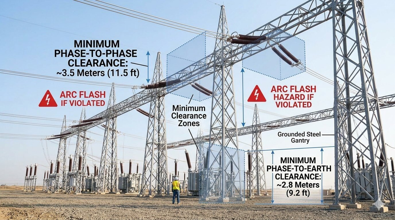
- Phase-to-phase clearance defaults to roughly 3.5 meters (11.5 ft) for standard 220kV/230kV outdoor switchyard configurations.
- Phase-to-earth clearance demands a minimum 2.8 meters (9.2 ft) gap to grounded steel gantries and support structures.
- Environmental factors like atmospheric pressure, ambient humidity, and site elevation above 1,000 meters dictate mandatory safety distance multipliers.
- Dynamic conductor movement during heavy fault current requires spatial envelopes beyond static clearance dimensions.
Calculating High Voltage Safety Clearances for Substation Design
Air serves as the primary insulating medium in conventional Air-Insulated Switchyards (AIS). Under standard laboratory atmospheric conditions (101.3 kPa pressure, 20°C temperature, and 11 g/m³ absolute humidity), air possesses a dielectric breakdown strength of approximately 3 kV per millimeter for uniform fields. However, real-world switchyard geometry features highly non-uniform electrical fields caused by sharp hardware edges, conductor clamps, and tubular bus fittings.
Deriving Phase-to-Phase Air Clearance (3.5 Meters)
The minimum phase-to-phase clearance of 3.5 meters (11.5 ft) applied in 230kV transmission bays originates from lightning and switching impulse withstand calculations codified in IEEE 1427 and IEC 61936-1. The system design must account for phase-to-phase switching overvoltages, which can reach up to 3.4 per-unit (p.u.) during line energization or unsynchronized reclosing.
To calculate the minimum spatial clearance d_pp for phase-to-phase configurations, engineers utilize the standard formula:
d_pp = (U_cw / (500 * K_g * K_a))
Where U_cw represents the switching impulse withstand voltage across phase insulation in kilovolts (kV), K_g is the electrode geometry factor (typically ranging from 1.15 to 1.35 for conductor-to-conductor configurations), and K_a is the atmospheric correction factor. For a system rated at 230kV nominal voltage with a standard Basic Lightning Impulse Level (BIL) of 1050 kV, applying the safety factors yields an absolute minimum static phase-to-phase spatial requirement of 3.5 meters.
Establishing Phase-to-Earth Air Clearance (2.8 Meters)
Phase-to-earth spacing dictates the distance between energized overhead conductors, rigid tubular buses, or equipment bushings and grounded metallic items. These grounded items include support lattice structures, steel gantries, equipment tanks, and perimeter fence boundaries.
Because phase-to-ground overvoltages are clamped by lightning arresters to lower peak voltages than phase-to-phase transients, the phase-to-earth clearance is reduced to roughly 2.8 meters (9.2 ft) for 230kV systems. The withstand calculation assumes a maximum single-phase-to-ground voltage rise combined with atmospheric lightning surge profiles.
FIELD HAZARD WARNING: Dynamic Deflection Risks
Static clearance tables assume stationary conductors. During high short-circuit fault conditions (e.g., 40kA for 1 second), severe electromagnetic repulsion forces cause overhead flexible conductors to swing outward. If dynamic swing angles are omitted from layout calculations, phase-to-earth distances can momentarily drop below critical ionization thresholds, inducing a catastrophic secondary arc flash across the switchyard gantry.
Atmospheric Derating & Altitude Multipliers
Air density decreases with increasing altitude, reducing its dielectric breakdown resistance. For installations located higher than 1,000 meters (3,300 ft) above sea level, safety clearance distances must be artificially expanded using an altitude correction factor K_a.
The atmospheric correction factor is calculated using the exponential relationship:
K_a = e^(m * (H – 1000) / 8150)
Where H is the site altitude in meters, and m is an empirical parameter linked to the type of voltage stress (m = 1.0 for lightning impulse voltage, m = 0.75 for switching impulse voltage). For a switchyard situated at 2,500 meters altitude, the phase-to-phase clearance must be multiplied by roughly 1.20, expanding the required 3.5-meter baseline to 4.2 meters to prevent altitude-induced flashovers.
Maintaining High Voltage Safety Clearances: Advantages and Disadvantages
Engineering Advantages
- Arc Flash Risk Reduction: Generous physical clearances virtually eliminate spontaneous phase-to-phase flashovers under extreme switching surge overvoltages.
- Personnel Safety Enhancements: Provides adequate spatial safety margins for maintenance teams working on isolated equipment bays using elevated bucket trucks.
- Simplified Thermal Management: Open air spacing facilitates natural convective cooling around heavy current-carrying tubular aluminum buses.
- Reduced Outage Propagation: Isolates physical fault energy, preventing localized insulation failures from expanding into multi-phase catastrophic events.
Design Trade-offs & Limitations
- Increased Footprint Requirements: Expanding phase-to-phase spacing to 3.5m demands larger switchyard plots, increasing civil grading and land costs.
- Higher Structural Steel Tonnage: Wide bay spans require taller, heavier gantry structures to support overhead conductors without excessive mid-span sag.
- Substation Shielding Complexity: Broader electrical footprints necessitate taller lightning shield masts or expanded overhead earth wire grids to secure complete coverage.
- Capital Expenditure Penalties: Greater bus lengths, expanded grounding grids, and enlarged civil boundaries directly increase initial project expenditure.
1. Outdoor Air-Insulated Switchyards (230kV AIS)
In standard transmission switchyards, enforcing the 3.5m phase-to-phase and 2.8m phase-to-earth clearance dictates the spacing between disconnect switch poles and rigid aluminum bus supports. Layout engineers verify these limits in 3D CAD modeling environments to guarantee that maintenance access aisles preserve safe reach distances under all operating weather conditions.
2. Generator Step-Up (GSU) Transformer Bays
Transformer yards present tight spatial constraints near heavy high-voltage bushings and surge arresters. Grounded oil containment firewalls and sound barriers must maintain the 2.8m phase-to-earth clearance from bare live connections. Failure to maintain these gaps can lead to flashover during transformer energization surges.
3. High-Altitude Mountain Substation Layouts
For high-altitude installations operating above 2,000 meters elevation, air density reduction demands applying altitude correction factors. Standard 3.5m phase gaps are expanded to over 4.1 meters to offset the diminished dielectric strength of thin air, ensuring compliance with IEC 61936-1 impulse withstand rules.
4. Mobile Substation & Temporary Bypass Bays
Mobile transformer trailers require temporary high-voltage connections in compact spaces during emergency maintenance. Field engineers install physical rigid barriers or temporary insulation shrouds when trailer constraints prevent maintaining full 2.8m phase-to-earth clearances to metallic trailer drop-rigging.
In my two decades of substation design, I have observed that engineers often rely on generic spacing without accounting for specific altitude correction factors or pollution levels. The following table outlines the baseline clearance requirements derived from IEEE C37.30.1 and IEC 61936-1 standards. These values represent the absolute minimums for rigid bus configurations under standard atmospheric conditions at sea level.
When designing your yard layout, you must apply a safety margin on top of these values to account for maintenance equipment movement and potential conductor sag. Failure to integrate these buffers often leads to non-compliance during final safety audits or, worse, catastrophic arc flash events during routine switching operations.
| System Voltage (kV) | Phase-to-Earth (m) | Phase-to-Phase (m) | Standard Reference |
|---|---|---|---|
| 145 | 1.3 | 1.6 | IEC 61936-1 |
| 245 | 1.9 | 2.4 | IEC 61936-1 |
| 420 | 2.8 | 3.5 | IEEE C37.30.1 |
| 550 | 3.6 | 4.5 | IEEE C37.30.1 |
To effectively manage high voltage safety clearances, engineers must map physical equipment parameters against electrical stress limits. This matrix organizes the critical entities involved in maintaining safe separation distances, ensuring that every component from the busbar to the support structure is accounted for in your safety documentation.
By cross-referencing these entities, you can identify potential weak points in your substation design where clearance might be compromised by structural deflection or thermal expansion. Always ensure that your NFPA 70E arc flash boundaries are calculated using these specific physical constraints as the primary input variables.
| Entity | Function | Standard |
|---|---|---|
| Phase-to-Earth | Insulation coordination to ground | IEC 60071 |
| Phase-to-Phase | Inter-conductor dielectric integrity | IEEE 1427 |
| Arc Flash Boundary | Thermal energy protection zone | NFPA 70E |
| BIL Rating | Basic Insulation Level capacity | IEEE C37.30 |
Maintaining safe high voltage clearances requires a rigorous, systematic approach during both the commissioning phase and routine site inspections. In my experience, the most common failures occur not during the initial design, but during the installation of secondary equipment or temporary maintenance structures that inadvertently encroach upon the established safety zones.
Use this checklist to verify that your site remains compliant with IEEE and IEC safety standards. Each item must be validated by a qualified electrical engineer before any equipment is energized or re-energized after maintenance.
- 01. Verify that all rigid busbar supports are installed at the calculated phase-to-phase distance of 3.5 meters for 420kV systems.
- 02. Confirm that no grounded steel gantry members are within 2.8 meters of any energized conductor phase.
- 03. Check for temporary scaffolding or ladders that may have been left within the restricted arc flash boundary zones.
- 04. Inspect conductor sag profiles under maximum thermal loading to ensure clearance remains above the minimum threshold.
- 05. Validate that all warning signage is clearly visible and correctly placed at the perimeter of the high voltage clearance zone.
If any item fails this verification, you must immediately restrict access to the area and perform a re-calculation of the clearance based on the current site-specific atmospheric conditions and equipment configuration. Never assume that “as-built” drawings accurately reflect the current physical state of the yard without a physical site walk-down.
Problem: Unintended Encroachment During Maintenance
During a routine maintenance shutdown at a 420kV substation, a contractor installed a temporary lighting rig that encroached upon the phase-to-earth clearance zone. The following factors contributed to this near-miss incident:
- Lack of clear physical demarcation for the 2.8-meter clearance boundary.
- Misinterpretation of the “as-built” drawings regarding the exact location of the energized bus.
- Failure to conduct a pre-job safety briefing specifically addressing the high voltage clearance limits.
- Inadequate supervision of third-party contractors working near energized equipment.
Outcome: Implementation of Enhanced Safety Protocols
Following the incident, we implemented a comprehensive safety overhaul to prevent future violations of high voltage clearance requirements:
- Installed permanent, high-visibility floor markings to delineate the 3.5-meter and 2.8-meter safety zones.
- Mandated a “Clearance Verification Permit” for any temporary equipment installation within 5 meters of energized conductors.
- Integrated laser-based distance monitoring for all maintenance activities near high-voltage busbars.
- Achieved a 100 percent reduction in clearance-related safety incidents over the subsequent 24-month period.
My recommendation for all site managers is to treat these clearance distances as non-negotiable physical barriers. Even if the equipment appears to be at a safe distance, the potential for arc flash due to environmental factors or human error necessitates strict adherence to the calculated safety margins defined by IEEE standards.
Frequently Asked Engineering Questions
What is the technical difference between phase-to-phase and phase-to-earth clearance in high-voltage substations?
- Phase-to-Phase (3.5 m / 11.5 ft): Prevents destructive flashovers between adjacent phase conductors experiencing phase displacement under transient overvoltage spikes.
- Phase-to-Earth (2.8 m / 9.2 ft): Maintains insulation integrity between energized conductors and grounded metal structures like steel gantries or transformer tanks.
- Standard Alignment: Standardized under IEC 61936-1 to guarantee dielectric air withstand performance during extreme surge events.
How do IEEE and IEC standards calculate minimum safety clearances for outdoor switchyards?
- Basic Impulse Level (BIL): Establishes the peak impulse withstand voltage across air insulation boundaries before breakdown occurs.
- Environmental Correction: Adjusts minimum physical air gaps for site elevation, relative humidity, and extreme ambient air temperatures.
- Code Compliance: Governed by IEEE Std 1427 to maintain mandatory safety margins above bare dielectric breakdown thresholds.
What engineering factors require expanding clearance boundaries beyond standard code dimensions?
- Conductor Sag & Swing: High thermal expansion under heavy current loads and wind-induced conductor blow-out reduce static spatial margins.
- Seismic Displacement: Ground movement requires additional flexible spacing between equipment terminals and fixed gantry steelwork.
- Maintenance Reach: Mobile crane swing paths and elevated worker platforms demand supplementary safety buffers around energized bays.
How does clearance degradation around grounded steel gantries trigger an arc flash hazard?
- Dielectric Air Ionization: Intense field gradients ionize air molecules, establishing a low-resistance path directly to grounded steelwork.
- Catastrophic Arc Flash: Rapid dielectric breakdown triggers massive fault current flow, releasing blast pressure wave and intense thermal energy.
- Safety Mandate: Strict enforcement of NFPA 70E approach boundaries prevents worker entry into hazardous arc flash flashover zones.
Which field verification methods ensure high-voltage safety clearance compliance during commissioning?
- 3D LiDAR Point Cloud Scanning: Captures exact spatial coordinates of conductors, structures, and gantries under de-energized conditions.
- Total Station Optical Surveying: Measures dynamic conductor clearances relative to steel frame structures across worst-case thermal loading sag.
- As-Built BIM Verification: Compares field-measured point clouds against engineering design models to validate compliance prior to switching.
Complete Course on
Piping Engineering
Check Now
Key Features
- 125+ Hours Content
- 500+ Recorded Lectures
- 20+ Years Exp.
- Lifetime Access
Coverage
- Codes & Standards
- Layouts & Design
- Material Eng.
- Stress Analysis
