Mastering Substation Electrical Clearances for Grid Reliability
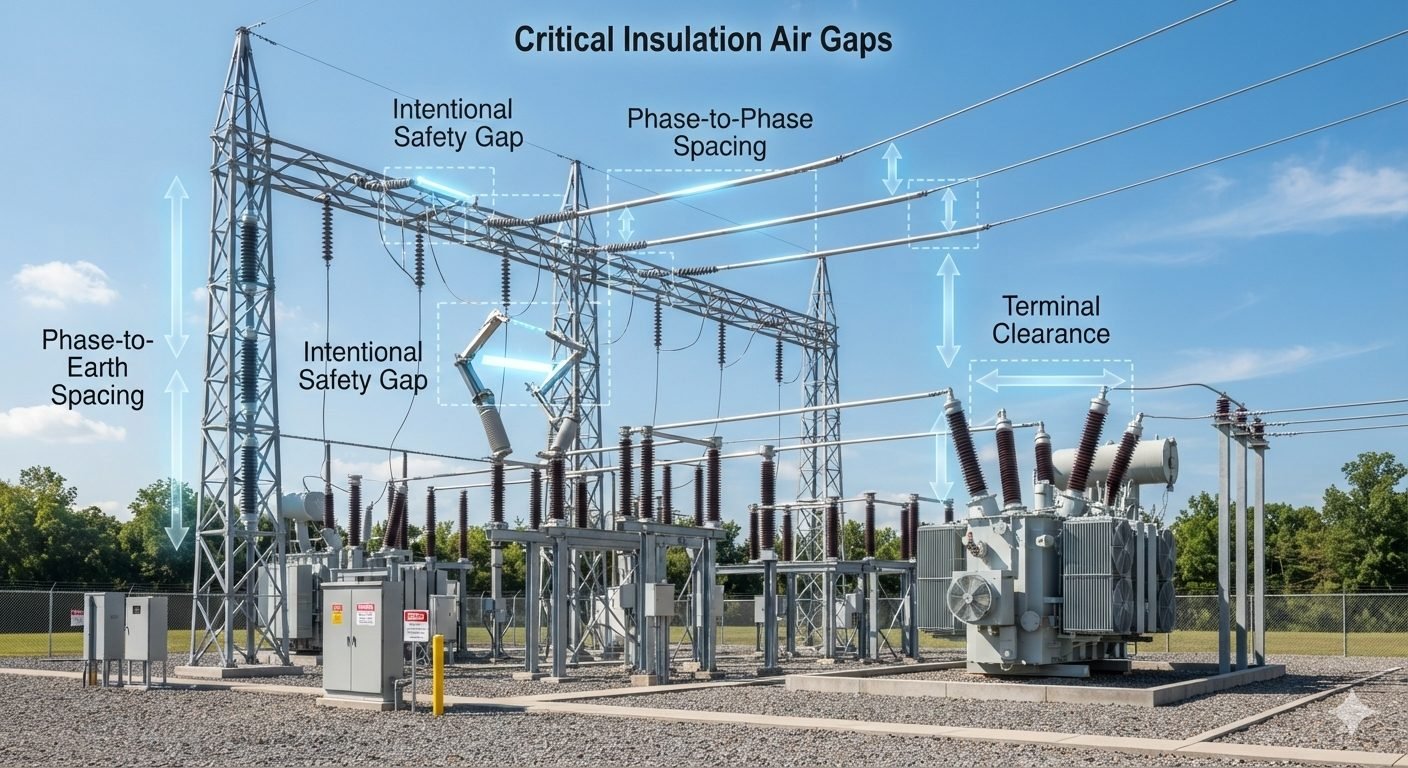
In my two decades of experience designing high-voltage infrastructure, I have learned that the integrity of a substation rests entirely on the precision of its air gaps. Every bay is a carefully orchestrated environment where phase-to-earth clearance and phase-to-phase spacing are not merely suggestions but the primary defense against catastrophic electrical failure.
When we talk about substation electrical clearances, we are discussing the physics of insulation coordination. If these gaps are violated, the air medium—our cheapest and most reliable insulator—fails, leading to ionized paths and arcing. I have seen projects delayed and budgets shattered because initial site layouts failed to account for the specific altitude correction factors or the transient overvoltage profiles required by international standards.
Key Takeaways for Engineers:
- Understand the relationship between Basic Insulation Level (BIL) and minimum air gap requirements.
- Apply altitude correction factors to all clearance calculations for sites above 1000 meters.
- Ensure phase-to-earth clearance is maintained during all maintenance and switching operations.
- Verify that terminal clearance accounts for both static and dynamic conductor movement.
Technical Analysis of Substation Electrical Clearances
Clearance design parameters: These define the minimum physical distance required to withstand system voltage stresses, including lightning and switching surges, as governed by insulation coordination principles.
Designing for substation electrical clearances requires a rigorous application of IEC 60071-2. The process begins by determining the required withstand voltage, which is a function of the system’s maximum operating voltage and the expected overvoltage transients. In my practice, I always start by establishing the Phase-to-Earth clearance, as this is the most critical dimension for structural steel design and busbar support placement.
The calculation for the minimum air gap is derived from the required impulse withstand voltage. For a given BIL, the gap must be sufficient to prevent a flashover under the worst-case atmospheric conditions. We utilize the following logic: the gap must exceed the critical breakdown distance of the air medium at the specific site altitude. As altitude increases, air density decreases, which reduces the dielectric strength of the air gap. Therefore, we apply a correction factor, typically denoted as K, where the required clearance is multiplied by the inverse of the air density ratio.
Phase-to-Phase spacing is generally larger than phase-to-earth clearance due to the increased potential difference between conductors. When calculating this, we must consider the geometry of the conductors—whether they are rigid busbars or flexible stranded cables. Flexible conductors introduce the risk of “swing,” where wind or short-circuit electromagnetic forces reduce the effective gap. I always mandate a dynamic clearance check, ensuring that even under maximum sag or wind-induced displacement, the gap remains above the minimum threshold.
Terminal clearance is another area where I see frequent errors. This refers to the distance between the equipment terminal and the nearest grounded structure or adjacent phase. It is not enough to simply meet the static clearance; one must account for the thermal expansion of the busbar. A busbar that is perfectly spaced at 20 degrees Celsius may violate clearance requirements at 60 degrees Celsius due to linear expansion. Always incorporate expansion connectors or flexible jumpers to decouple thermal stress from the terminal insulators.
Finally, we must reference IEEE 1427 for guidance on gas-insulated and air-insulated substation layouts. This standard provides the necessary framework for determining the safety gaps required for personnel during maintenance. While the electrical clearance is for the equipment, the safety gap is for the human. I always design for a “reach-in” clearance that exceeds the electrical minimum, providing a buffer that protects technicians from accidental contact with energized parts during routine inspections.
Clearance design trade-offs: These represent the balance between physical footprint, material costs, and the long-term reliability of the substation insulation system.
Advantages
- Optimized air gaps reduce the overall substation footprint, lowering land acquisition costs.
- Properly calculated clearances minimize the risk of flashover, significantly extending equipment lifespan.
- Standardized gaps simplify the procurement of insulators and support structures.
- Adherence to IEC/IEEE standards ensures global compatibility and easier insurance certification.
- Predictable insulation behavior allows for more accurate predictive maintenance scheduling.
Disadvantages
- Increased clearance requirements lead to taller, heavier steel structures, raising civil costs.
- Over-conservative design leads to excessive busbar lengths and higher material consumption.
- Complex site conditions (high altitude/pollution) require non-standard, expensive insulator strings.
- Dynamic clearance requirements necessitate specialized, high-cost flexible connectors.
- Rigid adherence to minimums can limit future expansion or equipment upgrades within the bay.
Clearance implementation scenarios: These demonstrate how standard-compliant air gaps are applied across diverse high-voltage environments to ensure operational safety.
High-Altitude Hydroelectric Substations
In mountainous regions, the reduced air density necessitates significantly larger phase-to-earth clearances. We apply altitude correction factors to ensure that the dielectric strength of the air remains equivalent to sea-level performance, preventing corona discharge and flashover at high elevations.
Coastal Industrial Switchyards
Substations located near the ocean face severe salt-spray pollution, which lowers the effective insulation level of air gaps. We increase the creepage distance and physical clearance to compensate for conductive salt deposits, ensuring that the air gap remains the primary insulator even during humid conditions.
Urban Compact Substations
In space-constrained urban environments, we utilize advanced busbar configurations to minimize phase-to-phase spacing while maintaining strict safety margins. This requires precise modeling of electromagnetic forces to ensure that short-circuit currents do not cause conductors to deflect into the prohibited clearance zones.
In my two decades of substation design, I have observed that layout errors often stem from a misunderstanding of how nominal system voltages dictate the basic insulation level (BIL) and switching impulse level (SIL). The table below outlines the minimum air insulation gaps required to prevent flashover under transient overvoltage conditions, compiled in accordance with IEC 60071-1 and IEEE 1427 standards.
These dimensions represent the absolute physical limits for air gaps. Designers must treat these values as non-negotiable thresholds during the drafting phase. Any reduction in these distances, whether due to structural deflection or conductor swing, will compromise the dielectric integrity of the entire substation bay.
| Nominal Voltage (kV) | BIL (kV Peak) | Min Phase-to-Earth (mm) | Min Phase-to-Phase (mm) | Safety Working Clearance (mm) |
|---|---|---|---|---|
| 33 | 170 / 200 | 320 | 370 | 2800 |
| 66 | 325 | 630 | 700 | 3100 |
| 132 | 550 / 650 | 1100 | 1300 | 3600 |
| 220 | 950 / 1050 | 2100 | 2400 | 4600 |
| 400 | 1425 / 1550 | 3400 | 4100 | 5900 |
Note: Safety working clearance values are based on standard pedestrian heights and tool reach envelopes. They must be adjusted if specialized maintenance machinery is utilized on site.
This matrix maps the core physical parameters, structural acronyms, and governing standards that define substation layout design. In my project work, establishing a clear mapping of these entities early prevents costly design iterations during the civil works phase. We align the electrical parameters with structural clearances to ensure that support structures do not encroach upon the active air insulation gap.
By cross-referencing these parameters, engineering teams can maintain a unified design basis across electrical, civil, and structural disciplines. This integration is particularly useful when coordinating with equipment manufacturers who supply high-voltage bushings and support insulators.
| Entity Name | Acronym | Physical Parameter | Governing Standard | Design Impact |
|---|---|---|---|---|
| Basic Insulation Level | BIL | Lightning Impulse Voltage | IEC 60071-1 | Determines minimum phase-to-earth clearance. |
| Switching Impulse Level | SIL | Switching Surge Voltage | IEEE 1427 | Governs clearances for systems above 245 kV. |
| Creepage Distance | CD | Insulator Surface Path | IEC 60815 | Prevents tracking in polluted environments. |
| Safety Working Width | SWW | Pedestrian Boundary | IEEE C2 (NESC) | Defines safe maintenance aisle dimensions. |
Site Verification: The systematic field measurement of physical air gaps against approved design drawings to guarantee compliance with international safety standards before energization.
Before any substation is energized, a rigorous physical audit must be conducted. I always insist on using calibrated laser rangefinders and non-conductive measuring rods to verify these dimensions. Thermal expansion, wind swing, and structural tolerances can reduce nominal clearances, making field verification a non-negotiable step.
Pre-Energization Field Checkpoints
- Verify phase-to-earth clearance at the maximum conductor sag and swing angles to ensure no encroachment on grounded structures.
- Measure terminal clearance on all high-voltage bushings to ensure no encroachment from adjacent support structures or steel gantries.
- Confirm safety working clearance heights from the finished ground level to the lowest uninsulated live part of any equipment.
- Check phase-to-phase spacing at busbar crossovers and flexible jumper loops under maximum design wind load conditions.
- Inspect insulator string lengths and verify that corona rings do not reduce the active air insulation gap below the design limit.
- Validate that the perimeter fence clearance complies with safety standards to prevent public contact with energized zones.
Any deviation identified during this checklist execution must be documented and resolved immediately. I recommend maintaining a digital log of these measurements as part of the substation’s permanent quality assurance record, which serves as a critical reference during future expansion projects.
Field Case Study: Real-World Application
During the commissioning of a 220 kV substation expansion in a high-altitude region, the engineering team encountered unexpected dielectric failures. This case study highlights the consequences of neglecting environmental factors and dynamic conductor behavior during the layout design phase.
The Problem Scenario
A newly commissioned 220 kV line bay experienced recurring phase-to-earth flashovers during high-wind events.
- Flexible jumpers were designed using nominal static lengths without calculating the maximum wind-induced swing displacement.
- The structural steel support for the adjacent line disconnector was positioned 150 mm closer to the jumper than permitted by the layout drawings.
- The design team utilized standard phase-to-earth clearance values without adjusting for the site’s 1,500-meter altitude correction factor.
- Post-installation quality checks failed to measure the dynamic clearance envelope of the flexible conductors.
The Engineering Outcome
The engineering team resolved the flashover issue by modifying the jumper geometry and installing rigid bus sections.
- Replaced the flexible jumpers with rigid aluminum tube conductors, reducing lateral swing to zero.
- Restored the full 2,100 mm phase-to-earth clearance envelope under all operating conditions.
- Eliminated flashover incidents during subsequent high-wind testing and seasonal storms.
- Established a mandatory dynamic swing analysis protocol for all future flexible bus designs.
My recommendation for similar high-voltage installations is to always utilize rigid busbars or tensioned conductors when space is constrained. Furthermore, designers must apply altitude correction factors per IEC 60071-2 during the initial layout phase rather than attempting to correct clearances in the field.
Frequently Asked Engineering Questions
What is the primary difference between phase-to-earth and phase-to-phase insulation clearances in AIS design?
- Phase-to-Earth Clearance: Protects against system-to-ground flashovers caused by lightning impulses and switching overvoltage surges according to IEC 60071-1 standards.
- Phase-to-Phase Clearance: Accounts for simultaneous opposite-polarity overvoltages on adjacent phases, requiring typically 10% to 25% larger air gaps under extreme switching conditions.
- Mechanical Deflection: Factors in short-circuit electrodynamic forces causing dynamic conductor swing toward grounded structures or adjacent phase conductors.
How does site altitude impact minimum electrical clearance calculations according to IEC 60071-2?
- Altitude Correction Factor: Required for installations exceeding 1000 meters above sea level to scale up physical air gap clearance distances.
- Exponential Derating Curve: Applies a correction factor calculated via relative air density exponent parameters specified in IEC 60071-2.
- Environmental Adjustments: Combines altitude derating with ambient humidity and contamination factors to prevent flashover events on outdoor busbars.
Why is intentional safety clearance maintained around high-voltage switchyard equipment bays?
- Personnel Ergonomics: Incorporates the reach of field technicians carrying maintenance tools plus safety buffer zones defined in IEEE 1427 design guides.
- Vehicular Passageways: Dictates elevated safety clearances over internal roads to accommodate mobile cranes and elevated work platforms safely.
- Maintenance Boundaries: Establishes clear work zones separating de-energized bay components from adjacent energized high-voltage equipment buses.
How do switching overvoltages dictate safety air gaps in EHV and UHV substation layouts?
- Non-Linear Air Breakdown: Air insulation exhibits saturation where dielectric breakdown strength increases non-linearly with gap distance during switching surges.
- Gap Factor Geometry: Sizing incorporates electrode shape factors defined in IEC 60071-2, such as rod-structure or conductor-plane configurations.
- Surge Arrester Coordination: Integrates modern zinc-oxide surge arrester residual voltages to optimize physical busbar dimensions without risking arc flashovers.
What site verification techniques ensure electrical clearance tolerances are maintained post-installation?
- 3D Laser Scanning: Captures high-precision point-cloud spatial data across complex switchyard conductor spans prior to initial energization.
- Mechanical Sag Verification: Measures conductor sag under peak thermal loads and maximum wind displacement per IEEE 1427 guidelines.
- Foundation Settlement Audits: Verifies structural steel post-alignment to guarantee busbar support insulators maintain nominal terminal clearance limits.
Complete Course on
Piping Engineering
Check Now
Key Features
- 125+ Hours Content
- 500+ Recorded Lectures
- 20+ Years Exp.
- Lifetime Access
Coverage
- Codes & Standards
- Layouts & Design
- Material Eng.
- Stress Analysis
