Table of Contents
What is Hydro Jetting and How Does It Work?
In my 20+ years of managing industrial piping systems, I have seen countless maintenance crews struggle with stubborn scaling, grease blockages, and invasive root systems. Traditional mechanical snaking often only punches a temporary hole through the obstruction, leaving behind a thick layer of debris that invites immediate re-clogging. This is where high-pressure water jetting becomes a game-changer for plant operators and municipal engineers alike.
By utilizing specialized reciprocating pumps and engineered nozzles, this process does not just clear blockages—it completely scours the internal pipe walls back to their original hydraulic profile. Whether you are dealing with a 2-inch process line in a chemical plant or a 48-inch municipal sewer main, understanding the fluid dynamics and mechanical limits of this technology is key to executing a safe, efficient cleaning campaign.
Key Engineering Takeaways
- Restores pipeline hydraulic capacity to near-original design specifications.
- Eliminates the risk of mechanical pipe wall gouging associated with steel snakes.
- Operates under strict compliance with ASME PCC-2 Article 501 for pressure testing and cleaning.
- Requires precise calculation of nozzle thrust and pipe hoop stress to prevent catastrophic line rupture.
- Serves as a necessary pre-requisite for high-accuracy inline inspection (ILI) and smart pigging runs.
Understanding the Mechanics of Hydro Jetting Systems
To truly appreciate how this process works, we must look at the underlying fluid mechanics. The system consists of a prime mover (usually a diesel engine), a high-displacement positive displacement pump, a high-pressure hose reel, and an engineered nozzle. The pump forces water through a restricted orifice, converting potential pressure energy into kinetic energy.
The velocity of the water jet exiting the nozzle can be calculated using the classic orifice flow equation:
Where:
• V = Jet exit velocity (m/s)
• C_d = Discharge coefficient of the nozzle orifice (typically 0.60 to 0.95 depending on geometry)
• P = Operating pressure differential across the nozzle (Pa)
• rho = Density of the fluid (approximately 1000 kg/m³ for water)
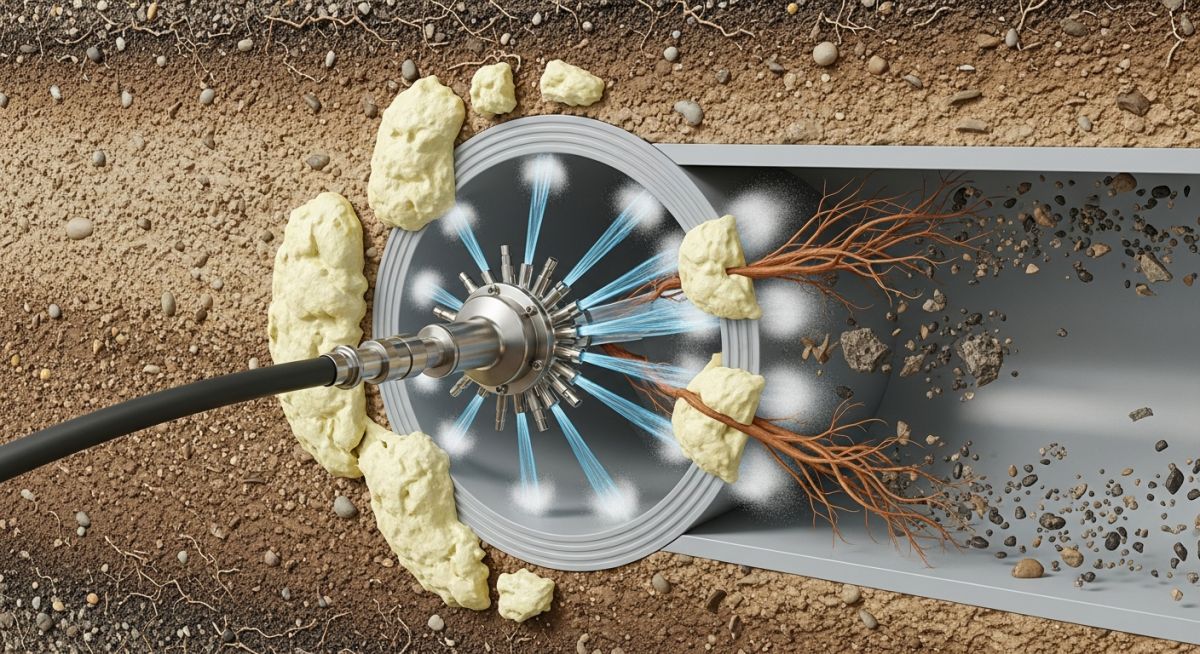
As this high-velocity jet strikes the deposit, it generates an impact pressure that exceeds the compressive strength of the scale or debris. Simultaneously, the rear-facing jets provide the necessary thrust force to propel the nozzle forward through the pipe. This thrust force (F) is calculated as:
Where A is the total cross-sectional area of the rear-facing orifices, and theta is the angle of the rear jets relative to the pipe centerline. Balancing this thrust against the hose drag is a key design step for long-distance runs.
In my field experience, selecting the correct nozzle angle is just as important as setting the pressure. A 15-degree rear jet angle provides maximum pulling power but limited wall-cleaning action. Conversely, a 45-degree angle offers excellent wall-scouring capabilities but significantly reduced forward thrust. Engineers must carefully select nozzle configurations based on the specific blockage profile and piping layout.
Engineering Parameters for Pipeline Jetting
The table below outlines the standard operating envelopes for various pipe materials and deposit types. These values are compiled from field data and align with recommendations from the WaterJet Technology Association (WJTA).
| Pipe Material | Nominal Diameter (in) | Max Safe Pressure (PSI) | Target Flow Rate (GPM) | Typical Target Deposit |
|---|---|---|---|---|
| PVC / HDPE | 4 to 12 | 4,000 | 12 to 25 | Silt, grease, soft roots |
| Cast Iron (Aged) | 6 to 24 | 8,000 | 30 to 60 | Rust scale, tuberculation |
| Carbon Steel | 2 to 48 | 15,000 | 40 to 120 | Calcium carbonate, hard polymers |
| Reinforced Concrete | 18 to 120 | 10,000 | 60 to 200 | Heavy silt, concrete slurry, roots |
Technical Mapping & Specifications Matrix
| System Entity | Acronym | Physical Parameter | Standard Reference |
|---|---|---|---|
| WaterJet Technology Association | WJTA | Safety guidelines & nozzle ratings | WJTA-IMCA Guidelines |
| Maximum Allowable Working Pressure | MAWP | Maximum system pressure limit | ASME Section VIII Div 1 |
| Inline Inspection | ILI | Post-cleaning wall thickness scan | API 1163 |
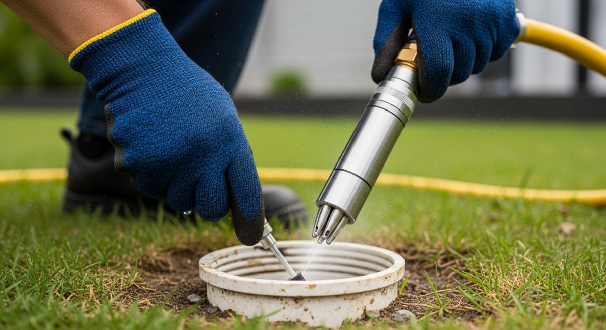
Field Verification and Safety Protocol
Before turning on the high-pressure pump, the field supervisor must verify every component of the jetting assembly. High-pressure water is extremely dangerous; a single pinhole leak in a hose at 20,000 PSI can easily cut through steel, let alone human flesh.
Mandatory Site Verification Steps
-
Hose Integrity: Inspect the entire length of the high-pressure hose for outer cover abrasions, exposed wire braid, or kinks. Replace immediately if any damage is found. -
Nozzle Orifice Check: Ensure all nozzle orifices are clear of debris and not worn out. Worn orifices drop system pressure and reduce cleaning efficiency. -
Safety Shroud Installation: Verify that a tough, flexible safety shroud is installed over the hose-to-nozzle connection to protect the operator from whip action. -
Pressure Relief Valves: Confirm that the pump’s mechanical relief valve and electronic burst discs are calibrated and set to trip at 10% above operating pressure. -
Exclusion Zone: Establish a physical barrier and “Danger: High Pressure Water Jetting” signage at a minimum radius of 15 feet around the work area.
Field Case Study: Real-World Application
The Problem: Severe Calcium Carbonate Scaling
A chemical processing facility in Texas experienced a 45% drop in flow capacity along a 1,200-foot section of a 12-inch carbon steel cooling water return line. Internal borescope inspection revealed a dense, crystalline calcium carbonate scale layer measuring up to 1.5 inches thick. Traditional chemical circulation was ruled out due to environmental disposal limits and the risk of localized acid corrosion on the aging pipe walls.
The Solution & Outcome: Targeted Hydro Jetting
Our engineering team specified a hydro jetting program utilizing a self-propelled rotary nozzle operating at 15,000 PSI with a flow rate of 85 GPM. We selected a 3D-rotating nozzle head with four radial jets offset at 45 degrees to shear the scale, and two rear jets at 15 degrees for forward propulsion.
The entire 1,200-foot run was cleaned in two passes over a 12-hour shift. Post-cleaning borescope inspection showed 100% scale removal with zero damage to the internal pipe wall. The system’s hydraulic flow coefficient (Hazen-Williams C-factor) was restored from an estimated 75 back to its original design value of 130, saving the plant over 180,000 in annual pumping energy costs.
Based on this project, my direct recommendation for any plant operator dealing with hard mineral scale is to perform a laboratory hardness test on a scale sample before selecting your jetting pressure. Knowing whether you are dealing with calcite, gypsum, or silica scale allows you to target the exact shear threshold, saving time and preventing unnecessary wear on your high-pressure equipment.
Frequently Asked Hydro Jetting Questions
What is the difference between hydro jetting and mechanical snaking?
Can hydro jetting damage older clay or concrete pipes?
How do you calculate the required water flow rate for large diameter pipes?
Is hydro jetting effective against heavy tree root intrusion?
What safety standards govern high-pressure water jetting operations?
Can chemicals be used in conjunction with hydro jetting?
Complete Course on
Piping Engineering
Check Now
Key Features
- 125+ Hours Content
- 500+ Recorded Lectures
- 20+ Years Exp.
- Lifetime Access
Coverage
- Codes & Standards
- Layouts & Design
- Material Eng.
- Stress Analysis

📚 Recommended Resources: hydro jetting
Related posts:
![An engineer performing an API 579 fitness for service assessment on an industrial pressure vessel.]()
How to Perform API 579 Fitness for Service Assessment
![3D CAD render of a bolted flange joint assembly showing a compressed gasket.]()
Understanding Gasket m and y Factors in Flange Design
![PASS/START-PROF 4.86 pipe stress analysis software interface displaying a 3D piping model.]()
PASS/START-PROF 4.86 Released: Discover the New Pipe Stress Analysis Capabilities
![ASME certification mark stamped on an industrial pressure vessel nameplate]()
What is ASME Certification? Procedure and Mark Explained
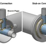
![Side-by-side comparison diagram of stub-in and stub-on piping branch connections.]()
Stub-in vs Stub-on Piping Connections: Engineering Design Guide
![A restriction orifice plate installed between pipe flanges in an industrial piping system.]()
What is a Restriction Orifice? Working, Types, and Sizing Guide