Table of Contents
What is a Link Seal and How to Install It
In my 20 plus years of piping engineering, I have seen countless field failures caused by poor wall penetration seals. Water ingress in a refinery basement or a municipal pump station is not just an inconvenience; it is a catastrophic risk to electrical systems and structural integrity. When traditional caulking, polyurethane foams, and mastic sealants fail under hydrostatic pressure, I always turn to a modular mechanical seal.
The industry standard for this is the Link Seal. It is a simple yet incredibly robust engineering solution consisting of interconnected rubber links that expand radially when their bolts are tightened. This expansion creates a permanent, high-pressure barrier that can withstand up to 20 psig of hydrostatic head. Let me walk you through the exact mechanics, sizing protocols, and field installation steps that I use to guarantee a leak-free penetration every single time.
Key Engineering Takeaways
- Provides a hydrostatic seal rated up to 40 feet of head pressure (20 psig).
- Absorbs shock, vibration, and acoustic noise within piping systems.
- Compensates for minor pipe misalignment and thermal expansion.
- Available in multiple elastomer grades (EPDM, Nitrile, Silicone) for chemical and temperature compatibility.
Why Use a Link Seal for Pipe Penetrations
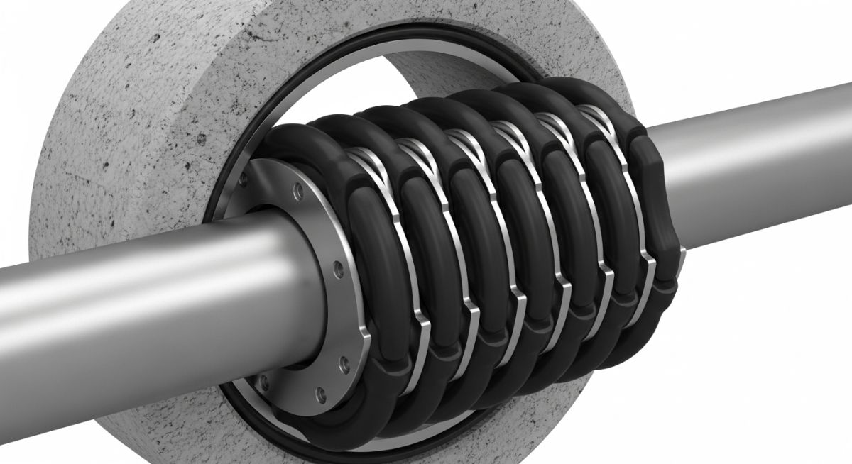
Modular Pipe Penetration Seals: High-performance elastomeric sealing elements linked together with metallic bolts that expand radially when tightened to fill the annular space between a pipe and its sleeve, ensuring long-term structural integrity under high hydrostatic pressure.
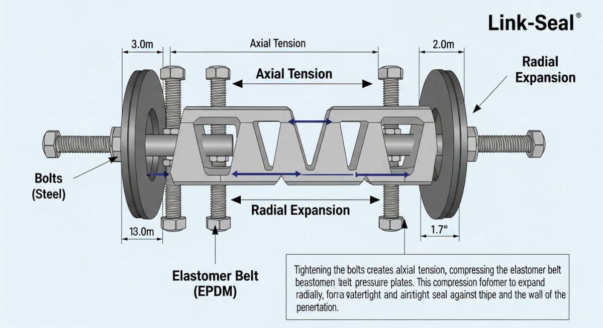
The fundamental working principle of a Link Seal relies on mechanical compression. When you tighten the bolts, the pressure plates on either side of the rubber link squeeze the elastomer. Because rubber is virtually incompressible, it expands radially outward against the casing sleeve and inward against the carrier pipe. This dual-sided radial expansion creates a continuous, high-pressure seal.
To ensure compliance with ASME B31.3 process piping codes, we must carefully calculate the annular space. The annular space is the physical gap between the outside diameter of the carrier pipe and the inside diameter of the wall sleeve.
The Annular Space Sizing Formula
To calculate the annular space, use the following formula:
Annular Space = (Sleeve Inside Diameter – Carrier Pipe Outside Diameter) / 2
For example, if you are running an 8-inch Schedule 40 steel carrier pipe through a 10-inch carbon steel sleeve:
- Carrier Pipe Outside Diameter (OD) = 8.625 inches
- Sleeve Inside Diameter (ID) = 10.020 inches
- Annular Space = (10.020 – 8.625) / 2 = 0.6975 inches
This calculated annular space of 0.6975 inches is then matched against the manufacturer’s sizing charts to select the correct link model (such as LS-300 or LS-315) and the exact number of links required to wrap around the pipe circumference.
Never use a Link Seal to support the weight of the carrier pipe. The seal is designed solely to create a hydrostatic barrier. If the pipe is not properly supported on both sides of the wall penetration using structural pipe hangers or concrete cradles, the pipe weight will compress the bottom links, causing the top links to pull away and leak.
Material Selection Criteria
Selecting the wrong elastomer is the leading cause of premature seal degradation. In my projects, I evaluate three primary environmental factors: chemical exposure, operating temperature, and cathodic protection requirements. For standard water and wastewater applications, EPDM rubber with carbon steel hardware is the industry baseline. However, if you are routing fuel lines, chemical process piping, or high-temperature steam lines, you must upgrade the elastomer and hardware to prevent chemical attack or thermal hardening.
Selecting the Right Link Seal Material
Link Seal Material Grades: Elastomeric compound classifications ranging from EPDM for water applications to Nitrile for hydrocarbons and Silicone for high-temperature environments, selected based on chemical compatibility and temperature limits.
| Model Grade | Elastomer Type | Bolt Material | Temperature Range | Primary Application |
|---|---|---|---|---|
| Grade C (Black) | EPDM | Carbon Steel (Zinc Dichromate) | -40°F to 250°F | Water, wastewater, HVAC, and general industrial piping. |
| Grade S-316 (Black) | EPDM | 316 Stainless Steel | -40°F to 250°F | Corrosive environments, marine applications, and buried pipelines. |
| Grade T (Green) | Nitrile (Buna-N) | Carbon Steel (Zinc Dichromate) | -40°F to 210°F | Hydrocarbons, fuels, oils, solvents, and organic solvents. |
| Grade T-S316 (Green) | Nitrile (Buna-N) | 316 Stainless Steel | -40°F to 210°F | Offshore platforms, refineries, and chemical processing plants. |
| Grade L (Grey) | Silicone | 316 Stainless Steel | -67°F to 400°F | High-temperature steam lines, fire-rated walls, and extreme cold. |
| Parameter / Entity | Acronym / Symbol | Standard Reference | Engineering Value / Limit |
|---|---|---|---|
| Hydrostatic Seal Pressure | P_h | ASME B31.3 | Up to 20 psig (40 feet of head pressure) |
| Annular Space Range | A_s | Manufacturer Specs | 0.5 inches to 4.0 inches (model dependent) |
| Bolt Torque Limit | T_b | ASTM F593 | 1.5 to 110 ft-lbs (varies by link size) |
| Shore A Hardness | Durometer | ASTM D2240 | 50 to 75 Shore A (depending on elastomer) |
Step-by-Step Link Seal Installation Checklist
Link Seal Installation Protocol: A systematic field verification procedure ensuring correct pipe centering, sleeve cleaning, bolt tightening sequence, and torque verification to prevent leakage in high-pressure penetrations.
Before you send your mechanical crew into the field, ensure they have this checklist in hand. In my experience, skipping even a single step—like failing to clean the sleeve interior—will result in a slow, weeping leak that is incredibly difficult to remediate once the system is pressurized.
Pre-Installation & Tightening Protocol
Remove all dirt, rust, concrete splatter, and sharp burrs from both the carrier pipe OD and the sleeve ID. Clean surfaces are mandatory for a tight elastomeric seal.
Ensure the carrier pipe is centered within the sleeve. Install permanent pipe supports on both sides of the wall to prevent load transfer onto the seal.
Connect the links to form a continuous belt around the pipe. The bolt heads must all face the installer (usually the wet side or accessible side of the wall).
Push the assembled chain into the gap. If the fit is tight, use a soapy water solution as a lubricant. Never use petroleum-based grease on EPDM links.
Tighten the bolts in a star pattern (similar to lug nuts on a car wheel). Do not tighten any single bolt fully in one go. Make 3 to 4 passes, gradually increasing torque.
Use a calibrated manual torque wrench to verify that all bolts meet the manufacturer’s specified torque limit. Look for uniform rubber bulging between the pressure plates.
Field Case Study: Real-World Application
During a municipal wastewater treatment plant expansion, a 12-inch ductile iron sludge line was routed through a 16-inch poured concrete wall. The contractor sealed the penetration using a standard polyurethane foam spray and a mastic wrap. Within three months of commissioning, seasonal groundwater levels rose, creating a 12-foot hydrostatic head. The foam seal failed completely, allowing over 50 gallons of water per hour to flood the dry well, threatening critical electrical control panels and variable frequency drives.
I was called to the site to design an emergency remediation plan. First, we temporarily dewatered the exterior wall. We then chipped out the failed foam and mastic sealant. Because the concrete core-drilled hole was slightly irregular, we installed a metallic wall sleeve anchored with non-shrink grout.
We calculated the annular space and specified a Grade S-316 Link Seal (EPDM with 316 Stainless Steel hardware to resist the corrosive wastewater environment). The crew installed the modular seal and tightened the bolts in a strict star pattern to 20 ft-lbs using a manual torque wrench. When the groundwater returned to its peak level, the penetration remained 100% dry. The dry well has now been operating leak-free for over five years.
My direct recommendation for any below-grade wall penetration is to completely avoid cheap chemical foam or caulk sealants. They degrade under cyclic thermal expansion and cannot withstand hydrostatic pressure. Always specify a modular mechanical seal during the design phase to avoid costly emergency field remediation later.
Frequently Asked Engineering Questions
What is the maximum hydrostatic pressure a Link Seal can withstand?
Can I use an impact wrench to tighten the bolts on a Link Seal?
How do I choose between EPDM and Nitrile Link Seals?
Do Link Seals provide electrical isolation for cathodic protection?
What happens if the core-drilled hole in the concrete is irregular?
Can a Link Seal accommodate pipe thermal expansion?
Complete Course on
Piping Engineering
Check Now
Key Features
- 125+ Hours Content
- 500+ Recorded Lectures
- 20+ Years Exp.
- Lifetime Access
Coverage
- Codes & Standards
- Layouts & Design
- Material Eng.
- Stress Analysis

📚 Recommended Resources: Link Seal
Read these Guides


Related posts:
![An engineer performing an API 579 fitness for service assessment on an industrial pressure vessel.]()
How to Perform API 579 Fitness for Service Assessment
![3D CAD render of a bolted flange joint assembly showing a compressed gasket.]()
Understanding Gasket m and y Factors in Flange Design
![PASS/START-PROF 4.86 pipe stress analysis software interface displaying a 3D piping model.]()
PASS/START-PROF 4.86 Released: Discover the New Pipe Stress Analysis Capabilities
![ASME certification mark stamped on an industrial pressure vessel nameplate]()
What is ASME Certification? Procedure and Mark Explained
![Professional technician inserting a high-pressure hydro jetting nozzle into a sewer pipe cleanout.]()
What is Hydro Jetting and How Does It Work?
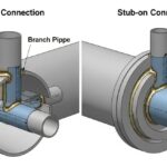
![Side-by-side comparison diagram of stub-in and stub-on piping branch connections.]()
Stub-in vs Stub-on Piping Connections: Engineering Design Guide