What is Pipe Bevelling and Why Does It Matter?
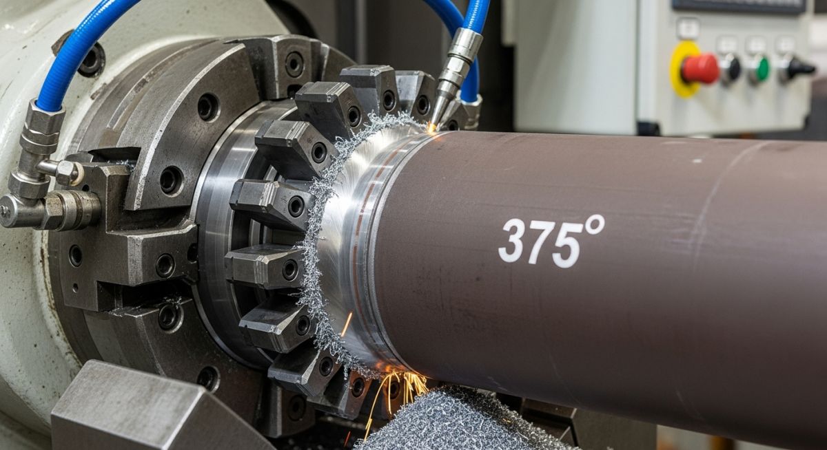
In my 20 plus years of managing piping projects across petrochemical plants and offshore platforms, I have seen many weld failures that could be traced back to poor end preparation. When we talk about high-pressure piping, you cannot simply butt two square-cut pipes together and expect a weld to hold up under 150 bars of operating pressure. That is where the art and science of edge preparation come into play. Shaping the pipe end is not just a preliminary step; it is the foundation of the entire joint’s mechanical integrity.
Whether you are working with heavy-wall carbon steel or sensitive duplex stainless steel, selecting the correct angle, root land, and preparation method directly dictates your welding efficiency and joint longevity. In this guide, I will share the practical field insights, calculations, and standards that define professional edge preparation in modern industrial piping.
Key Takeaways
- Understand how bevel geometry directly influences weld metal volume and heat input.
- Learn the differences between mechanical cold cutting, flame cutting, and plasma preparation.
- Master the standard tolerances specified by ASME B16.25 for butt-welding ends.
- Discover how to prevent work hardening when preparing corrosion-resistant alloys.
How Pipe Bevelling Ensures High Integrity Welds
When we design a weld joint, our primary goal is to achieve full penetration while minimizing the heat-affected zone (HAZ) and the volume of filler metal required. If the bevel angle is too wide, we waste expensive filler wire and introduce excessive heat, which leads to distortion and grain growth. If the angle is too narrow, the welder cannot access the root of the joint, resulting in lack of penetration or slag inclusions.
The Mathematics of Bevel Geometry
Let us look at the cross-sectional area calculation for a standard single-V bevel. This calculation is what I use to estimate weld metal consumption and plan consumable procurement for major projects.
The total cross-sectional area (A) of a single-V joint with a root gap can be calculated using this formula:
Where:
- t = Pipe wall thickness (mm)
- f = Root land thickness (mm)
- g = Root gap width (mm)
- theta = Total included angle (degrees)
Real-World Calculation Example:
Consider a 12-inch Schedule 40 carbon steel pipe. According to ASME B36.10M, the nominal wall thickness (t) is 10.31 mm. We are using a standard 37.5-degree bevel angle (which gives a 75-degree included angle, theta), a 1.6 mm root land (f), and a 2.4 mm root gap (g).
Step 1: Calculate the depth of the bevel portion
Depth = t – f = 10.31 mm – 1.6 mm = 8.71 mm
Step 2: Calculate the area of the two triangular bevel zones
Bevel Angle (alpha) = theta / 2 = 37.5 degrees
tan(37.5) = 0.7673
Area_bevel = 2 * [0.5 * 8.71 * 8.71 * 0.7673] = 75.86 * 0.7673 = 58.21 mm²
Step 3: Calculate the area of the rectangular root gap zone
Area_gap = g * t = 2.4 mm * 10.31 mm = 24.74 mm²
Step 4: Sum the areas for the total cross-sectional area
Total Area = 58.21 mm² + 24.74 mm² = 82.95 mm²
Step 5: Calculate weld metal volume per meter of weld
Volume = 82.95 mm² * 1000 mm = 82,950 mm³ = 82.95 cm³ per meter
By knowing this volume, we can multiply it by the density of carbon steel (approximately 7.85 g/cm³) to determine that we need about 651 grams of deposited weld metal per meter of joint. Factoring in a deposition efficiency of 70% for Shielded Metal Arc Welding (SMAW), we can accurately order 930 grams of electrodes per meter of weld. This level of planning prevents material shortages and keeps our projects on schedule.
In my years on site, I have seen many fabricators try to speed up fit-up by leaving a razor-sharp edge (zero root land). This is a recipe for disaster. Without a proper root land (typically 1.6 mm to 2.4 mm), the intense heat of the welding arc will blow through the root, causing excessive penetration, icicles inside the pipe, and severe root oxidation. Always enforce the root land specifications detailed in your Welding Procedure Specification (WPS).
Understanding Bevel Profiles
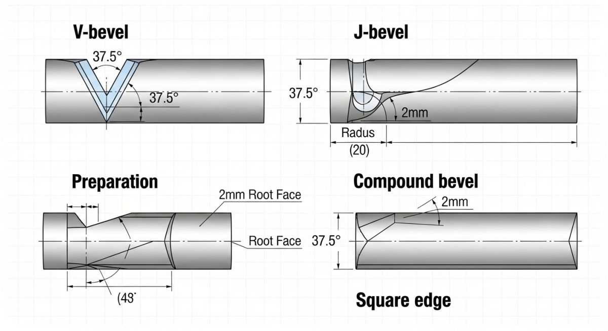
Different wall thicknesses and service conditions require different bevel profiles. Let us break down the three most common profiles used in industrial piping:
- Single-V Bevel: The workhorse of the piping industry. It is simple to cut and ideal for wall thicknesses up to 20 mm. It typically features a 37.5-degree bevel angle.
- Compound V-Bevel: Used on heavy-wall piping (typically over 20 mm to 22 mm) to reduce the volume of weld metal. It starts with a steep angle (often 37.5 degrees) and transitions to a shallower angle (such as 10 to 15 degrees) for the outer portion of the wall.
- J-Bevel and U-Bevel: These profiles feature a curved radius at the root. They are highly favored in automatic orbital welding because they provide a uniform root land and a consistent joint width, allowing for precise control of the weld pool.
The following table outlines the standard bevel configurations based on wall thickness in accordance with ASME B16.25. These parameters are critical for ensuring proper fit-up and weld quality.
| Wall Thickness (t) | Bevel Type | Bevel Angle (deg) | Root Land (mm) | Root Gap (mm) |
|---|---|---|---|---|
| Under 3 mm | Square Cut (No Bevel) | 0° | N/A | 1.0 to 1.6 |
| 3 mm to 22 mm | Single-V Bevel | 37.5° (±2.5°) | 1.6 (±0.8) | 1.6 to 3.2 |
| Over 22 mm | Compound V-Bevel | 37.5° to 10° transition | 1.6 (±0.8) | 2.0 to 3.2 |
| Heavy Wall (Critical) | U-Bevel / J-Bevel | 20° bevel, 5° slope | 1.6 to 2.4 | 1.6 to 2.4 |
This matrix maps the primary preparation methods against material compatibility, speed, and code compliance to help you select the right approach for your project.
| Method | Primary Materials | HAZ Risk | Precision Level | Code Reference |
|---|---|---|---|---|
| Cold Cutting (Mechanical) | All (CS, SS, Duplex, Alloys) | None (No heat applied) | Very High (±0.5°) | ASME B31.3 Cl. 328.4 |
| Oxy-Fuel Flame Cutting | Carbon Steel only | High (Requires grinding) | Moderate | AWS D1.1 Sec. 5.14 |
| Plasma Arc Cutting | CS, SS, Aluminum | Medium (Requires light prep) | High | ASME Sec IX QW-402 |
| Hand Grinding | Small diameter, low pressure | Low (Localized heat) | Low (Operator dependent) | Field touch-ups only |
Field Inspection Checklist for Pipe Bevelling
Before you allow any welder to strike an arc, you must verify that the joint preparation meets the exact requirements of your project’s WPS. In my experience, taking five minutes to check the bevel with a bridge cam gauge can save you thousands of dollars in cut-outs and repairs later.
Pre-Welding Bevel Verification Steps
-
Verify Bevel Angle: Use a calibrated bevel gauge to confirm the angle is within the specified tolerance (typically 37.5 degrees ±2.5 degrees for standard V-bevels).
-
Measure Root Land: Ensure the root land is uniform around the entire circumference. A variation of more than 0.8 mm can lead to uneven penetration.
-
Check Surface Cleanliness: The bevel face and adjacent pipe surfaces (at least 25 mm back from the weld prep) must be completely free of rust, scale, oil, grease, paint, and moisture.
-
Inspect for Lamination: Visually check the cut edge of the pipe for laminations, cracks, or inclusions. If found, the pipe must be cut back to sound metal.
-
Confirm Material Separation: Ensure that carbon steel tools (such as grinding discs or wire brushes) have not been used on stainless steel or duplex alloys to prevent cross-contamination.
Field Case Study: Real-World Application
The Problem: High Reject Rates on a Duplex Stainless Steel Pipeline
During a fast-track offshore gas platform project, the fabrication yard reported a 14% weld rejection rate on 8-inch Schedule 80 duplex stainless steel (UNS S31803) piping. The welds, executed via gas tungsten arc welding (GTAW), consistently failed radiographic testing due to root lack of fusion and micro-cracking.
Upon visiting the site, I discovered the sub-contractor was using hand-held plasma torches to cut the pipes, followed by manual grinding to establish the 37.5-degree bevel. This manual process resulted in highly irregular root lands and introduced localized heat-affected zones before the actual welding even began. The manual grinding also caused localized work hardening of the duplex material, making it highly resistant to proper weld fusion.
The Solution & Outcome: Transition to Cold Cutting
I immediately halted the manual preparation and mandated the use of split-frame mechanical cold-cutting machines (commonly known as clamshells). These machines cut and bevelled the pipe simultaneously without introducing any heat. We established a strict J-bevel profile with a 20-degree bevel angle and a 1.6 mm radius, which is ideal for duplex alloys.
The results were immediate. The weld rejection rate dropped from 14% to less than 0.5% within the first week of implementation. Because the cold-cutting machine produced a perfectly uniform root land and bevel angle, the welders were able to maintain a highly stable weld pool. Additionally, eliminating the pre-weld thermal stress from plasma cutting completely resolved the micro-cracking issues.
My direct recommendation for any project involving high-alloy or corrosion-resistant piping is to completely ban thermal cutting for weld preparation. The investment in mechanical cold-cutting equipment pays for itself almost instantly by eliminating weld repairs, reducing gas consumption, and saving hundreds of man-hours.
Frequently Asked Engineering Questions
Why is cold cutting preferred over flame cutting for pipe preparation?
What is a compound bevel and when should I use it?
How does ASME B16.25 govern pipe end preparation?
Can I use the same bevelling tools for carbon steel and stainless steel?
What is the typical tolerance for a root land in high-pressure piping?
How do you prepare thin-walled tubing for orbital welding?
Complete Course on
Piping Engineering
Check Now
Key Features
- 125+ Hours Content
- 500+ Recorded Lectures
- 20+ Years Exp.
- Lifetime Access
Coverage
- Codes & Standards
- Layouts & Design
- Material Eng.
- Stress Analysis