What is a Hazardous Environment? Industrial Types and Safeguarding Methods
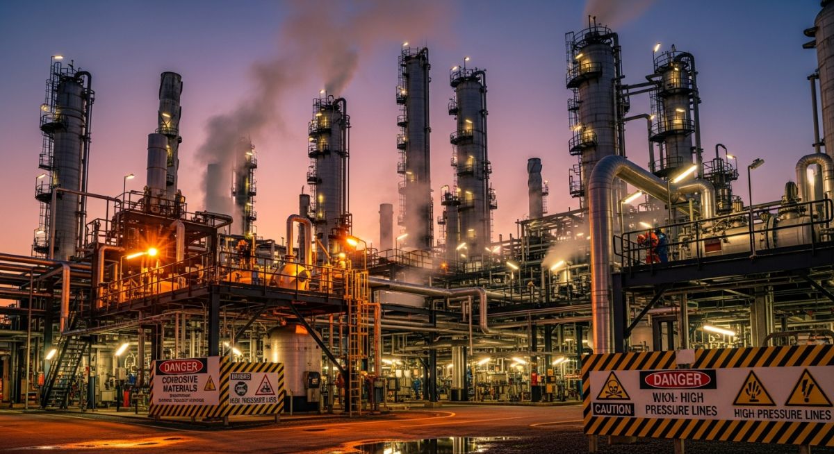
In my 20+ years of experience designing piping systems and chemical process plants, I have stood on offshore platforms and refinery floors where a single spark could lead to a catastrophic event. Understanding what constitutes a hazardous environment is not just a theoretical exercise; it is a fundamental safety requirement that dictates every engineering decision we make. From selecting the correct valve trim to routing electrical conduits, every detail must be engineered to isolate potential ignition sources from volatile atmospheres.
When we talk about these specialized areas, we are looking at complex interactions between chemical properties, physical containment, and environmental variables. Over the years, I have seen how minor oversights in area classification can lead to costly retrofits or, worse, system failures. This guide draws on real-world field experience to break down the classifications, calculations, and safeguarding methodologies required to keep your facility safe and compliant.
Key Engineering Takeaways
- Understand the critical differences between Class/Division and Zone classification systems.
- Learn how to calculate dilution ventilation rates to mitigate explosive gas accumulation.
- Identify the correct safeguarding methods, including explosion-proof enclosures and intrinsic safety barriers.
- Implement a robust field verification checklist to ensure long-term compliance and safety.
Defining a Hazardous Environment in Industry
Hazardous Environment Classifications: The systematic categorization of industrial workspaces based on the properties and likelihood of flammable substances present in the atmosphere. This framework dictates the selection of explosion-proof equipment and piping design parameters under API RP 500 guidelines.
To design a safe plant, we must first identify the specific hazards present. The industry categorizes these environments using two primary systems: the traditional North American Class/Division system and the international IEC/ATEX Zone system. Both systems evaluate the type of hazardous material and the probability of its presence in the atmosphere.
The Class and Division Framework
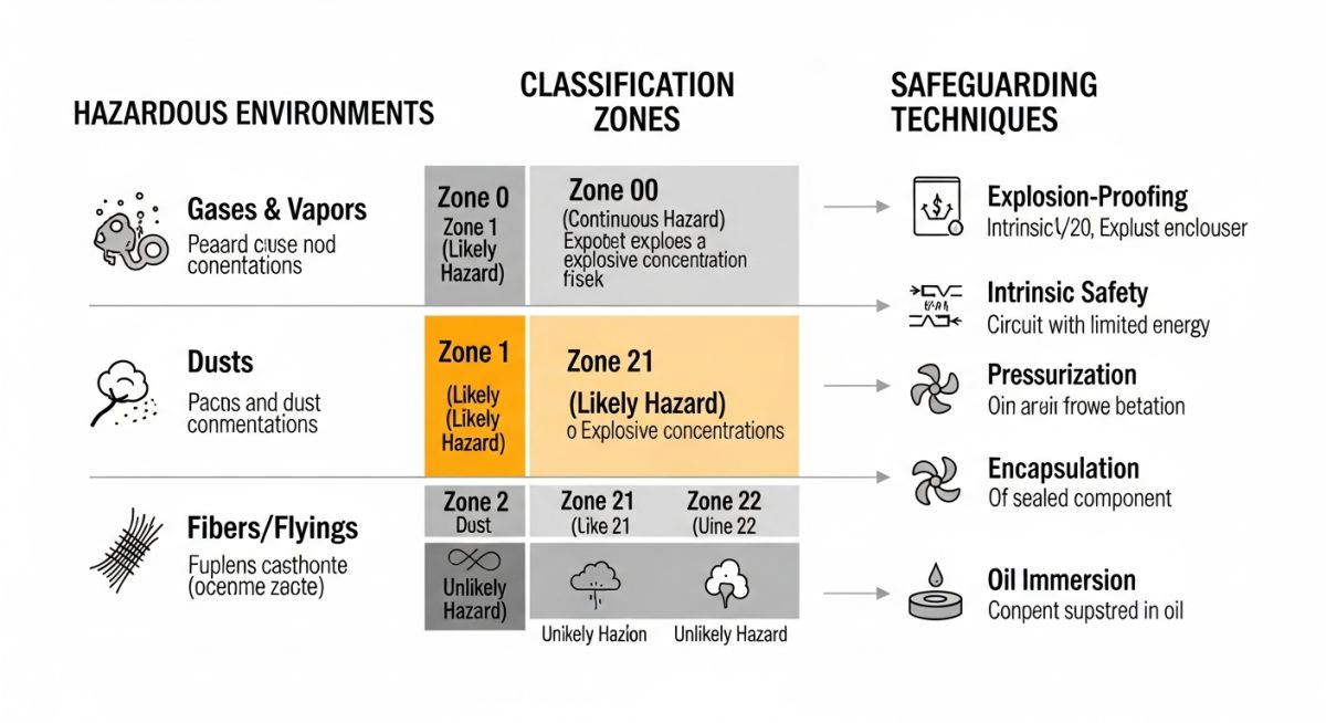
The Class/Division system, defined by the National Electrical Code (NEC) Article 500, separates hazards into three distinct classes based on their physical state:
- Class I: Flammable gases, vapors, or liquids (e.g., hydrogen, gasoline, methane).
- Class II: Combustible dusts (e.g., coal dust, flour, magnesium).
- Class III: Ignitable fibers or flyings (e.g., cotton, wood shavings).
Each Class is further divided into two Divisions based on the likelihood of the hazard being present:
- Division 1 (Normal Conditions): The hazard exists continuously, intermittently, or periodically during normal operations, maintenance, or leakage.
- Division 2 (Abnormal Conditions): The hazard is only present during abnormal conditions, such as a vessel rupture, pipe failure, or ventilation system breakdown.
The Zone Classification System
The international Zone system, governed by IEC 60079 and ATEX directives, provides a more granular approach by splitting the probability of hazard presence into three distinct zones:
- Zone 0 (Gases) / Zone 20 (Dusts): Explosive atmospheres are present continuously or for long periods (more than 1,000 hours per year).
- Zone 1 (Gases) / Zone 21 (Dusts): Explosive atmospheres are likely to occur in normal operation occasionally (10 to 1,000 hours per year).
- Zone 2 (Gases) / Zone 22 (Dusts): Explosive atmospheres are not likely to occur in normal operation, and if they do, will persist for a short period only (less than 10 hours per year).
Classifying Every Hazardous Environment Safely
Hazardous Area Classification: The engineering process of analyzing and classifying the environment where explosive gas or dust atmospheres may occur, ensuring the correct installation of electrical and mechanical apparatus. This process relies heavily on IEC 60079-10-1 standards for gas atmospheres.
To safely manage these areas, we must perform rigorous engineering calculations. One of the most common tasks is calculating the required dilution ventilation rate to prevent a localized gas release from reaching its Lower Explosive Limit (LEL).
Engineering Calculation: Dilution Ventilation Rate
To calculate the required dilution ventilation rate (Q) in cubic feet per minute (CFM) to maintain a gas concentration below 25% of the LEL, we use the following formula:
Where:
- Q: Required ventilation rate (CFM)
- R: Chemical release rate (lbs/min)
- S: Safety factor (typically 4 for continuous monitoring, up to 10 for unmonitored areas)
- M: Molecular weight of the gas (g/mol)
- LEL: Lower Explosive Limit of the gas (% by volume)
- D: Dilution factor (typically 1.0 for perfect mixing, up to 2.0 for poor mixing)
Let us look at a practical example. Suppose we have a localized methane release in a compressor shelter. The release rate (R) is estimated at 0.05 lbs/min. Methane has a molecular weight (M) of 16.04 g/mol and an LEL of 5.0%. We will use a safety factor (S) of 4 and a dilution factor (D) of 1.2 to account for non-ideal mixing.
Q = 81,800,000 / 96.24
Q = 849,958 CFM
This calculation shows that a massive volume of air is required to dilute even a small, continuous release of methane. In practice, this highlights why we rely on physical containment, closed-loop piping systems, and explosion-proof equipment rather than ventilation alone to mitigate risks in a hazardous environment.
Comparing Global Area Classification Standards
Standardization Comparison: The alignment of North American Class/Division systems with international IEC/ATEX Zone systems to establish equivalent safety levels across global engineering projects. This comparison is governed by ISA 60079 standards.
| Hazard Type | NEC Class/Division | IEC/ATEX Zone | Typical Presence Frequency | Equipment Protection Level (EPL) |
|---|---|---|---|---|
| Gas / Vapor | Class I, Division 1 | Zone 0 or Zone 1 | Continuous or Intermittent | Ga or Gb |
| Gas / Vapor | Class I, Division 2 | Zone 2 | Abnormal / Short duration | Gc |
| Combustible Dust | Class II, Division 1 | Zone 20 or Zone 21 | Continuous or Intermittent | Da or Db |
| Combustible Dust | Class II, Division 2 | Zone 22 | Abnormal / Short duration | Dc |
| Protection Concept | Designation | Primary Standard | Operating Principle | Typical Application |
|---|---|---|---|---|
| Explosion Proof | Ex d / XP | IEC 60079-1 | Contains internal explosion; cools escaping gases | Motors, junction boxes, switchgear |
| Intrinsic Safety | Ex i / IS | IEC 60079-11 | Limits electrical and thermal energy below ignition point | Sensors, transmitters, instrumentation |
| Purged / Pressurized | Ex p | NFPA 496 | Maintains positive pressure with clean air/inert gas | Control rooms, large analyzer shelters |
| Increased Safety | Ex e | IEC 60079-7 | Prevents arcs, sparks, and hot surfaces under normal use | Terminal boxes, luminaires |
Verifying Safety in Extreme Environments
Site Verification Protocol: The mandatory field inspection and testing sequence executed prior to commissioning equipment in classified locations to guarantee compliance with NFPA 70B.
Before any plant startup, I personally lead a walkdown of the classified areas. It is during these walkdowns that we catch critical installation errors that could compromise the entire safety system. Below is the checklist I use to verify compliance in the field.
Pre-Commissioning Field Checklist
Field Case Study: Real-World Application
The Problem: Solvent Recovery Unit Ignition Risk
During a routine safety audit at a chemical processing plant, we discovered that a solvent recovery unit handling toluene was classified as a Class I, Division 2 area. However, due to frequent seal failures on the transfer pumps, localized concentrations of toluene vapor regularly exceeded the LEL during normal operations. The existing non-explosion-proof instrumentation and standard junction boxes posed an immediate, catastrophic ignition risk.
The Outcome: Re-Engineering and Safeguarding
I led the engineering team to immediately re-classify the pump area as Class I, Division 1. We replaced the standard transfer pumps with canned motor pumps to eliminate shaft seals. All electrical junction boxes were upgraded to heavy-duty cast aluminum explosion-proof (Ex d) enclosures, and the instrumentation was re-wired through intrinsic safety (Ex i) barriers located in a safe control room. This comprehensive upgrade eliminated the ignition source, reduced fugitive emissions, and brought the facility into full compliance with NFPA 70.
This case study highlights the importance of dynamic risk assessment. Area classifications are not static; they must reflect the actual operating conditions and maintenance realities of the plant.
Frequently Asked Engineering Questions
What is the difference between Class I, Division 1 and Class I, Division 2?
Can I use ATEX Zone-rated equipment in a Class/Division facility?
What is an explosion-proof enclosure and how does it work?
What is the purpose of a conduit seal fitting?
How does intrinsic safety differ from explosion-proof protection?
What is a Temperature Class (T-code) and why is it critical?
===
Complete Course on
Piping Engineering
Check Now
Key Features
- 125+ Hours Content
- 500+ Recorded Lectures
- 20+ Years Exp.
- Lifetime Access
Coverage
- Codes & Standards
- Layouts & Design
- Material Eng.
- Stress Analysis
