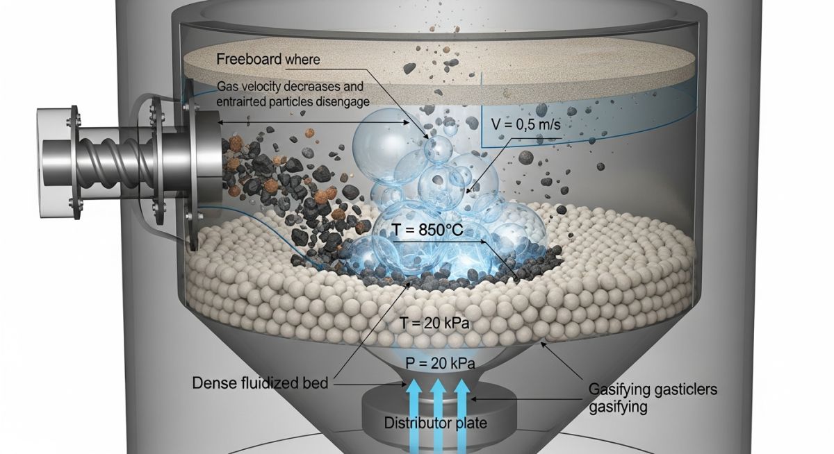
How to Control Bubbling Fluidized Bed Gasifier Variables Effectively
In my 20 years of commissioning thermal conversion systems, I have seen many operators struggle with bed defluidization and poor syngas quality. Managing a bubbling fluidized bed gasifier is not just about feeding biomass and blowing air; it is a delicate balancing act of thermodynamics and fluid dynamics. When you adjust one parameter, you trigger a cascade of physical and chemical changes throughout the reactor.
My experience on the field has taught me that understanding how these parameters interact is the difference between a highly efficient, continuous process and an unscheduled, costly shutdown. In this guide, we will break down the core operating parameters, analyze their mathematical relationships, and look at real-world field data to help you optimize your gasification plant.
Key Engineering Takeaways
- Maintain bed temperatures strictly between 800°C and 900°C to balance tar cracking with ash fusion limits.
- Keep the Equivalence Ratio (ER) within the 0.20 to 0.33 range to prevent shifting from gasification to complete combustion.
- Ensure the operating fluidization velocity is kept at 2 to 4 times the minimum fluidization velocity (U_mf) to guarantee robust gas-solid mixing.
- Utilize active bed materials like olivine or dolomite to provide in-situ catalytic tar reduction without downstream pressure drops.
- Design gasifier piping and nozzle configurations in strict compliance with ASME B31.3 to handle thermal expansion and abrasive particulate flows.
Why Bubbling Fluidized Bed Gasifier Variables Dictate Performance
To achieve stable gasification, we must control several interconnected parameters. Each variable directly influences the chemical reaction pathways (such as partial oxidation, steam reforming, and the water-gas shift reaction) and the physical behavior of the fluidized bed. Let us analyze these parameters in detail.
1. Bed Temperature
Bed temperature is the most influential thermodynamic parameter. Higher temperatures accelerate endothermic gasification reactions, which increases the production of hydrogen (H2) and carbon monoxide (CO) while reducing tar content. However, the upper limit is strictly constrained by the ash melting point of your biomass feedstock.
If the temperature exceeds this limit (often around 900°C to 950°C for agricultural residues), the ash begins to soften and stick to the bed material. This leads to channel formation, loss of fluidization, and eventually, a complete system shutdown.
2. Equivalence Ratio (ER)
The Equivalence Ratio (ER) is defined as the ratio of the actual oxygen supplied to the stoichiometric oxygen required for complete combustion:
An ER of 0 means pure pyrolysis, while an ER of 1.0 represents complete combustion. For bubbling fluidized bed gasifiers, the optimum ER lies between 0.20 and 0.33. If you increase the ER beyond 0.33, you introduce too much oxygen, which burns the useful syngas (CO and H2) into carbon dioxide (CO2) and water (H2O), lowering the heating value of the gas.
3. Steam-to-Biomass Ratio (SBR)
Injecting steam as a gasifying agent introduces water molecules that drive the water-gas shift and steam reforming reactions:
Steam Reforming: CH4 + H2O <=> CO + 3H2 (Endothermic)
Increasing the SBR (typically kept between 0.4 and 1.0) significantly boosts the hydrogen content of the syngas. However, because steam reforming is highly endothermic, adding too much steam without an external heat source will cool the bed, slowing down the overall reaction kinetics.
In my field operations, I have observed that using standard silica sand with high-potassium biomass (like straw or empty fruit bunches) leads to rapid bed agglomeration. Potassium reacts with silica to form low-temperature eutectic silicates that melt as low as 700°C. Always specify alternative bed materials like olivine sand or calcined dolomite when gasifying high-alkali biomass.
Hydrodynamic Calculations: Minimum Fluidization Velocity
To maintain a bubbling bed, the gas velocity must exceed the minimum fluidization velocity (U_mf). We calculate this using the Ergun equation simplified for small particles (where the Reynolds number is less than 20):
Where:
– d_p = mean particle diameter of the bed material (m)
– rho_s = density of the solid bed material (kg/m³)
– rho_g = density of the gasifying gas (kg/m³)
– g = acceleration due to gravity (9.81 m/s²)
– mu = dynamic viscosity of the gas (Pa·s)
– epsilon_mf = bed voidage at minimum fluidization (typically 0.4 to 0.45)
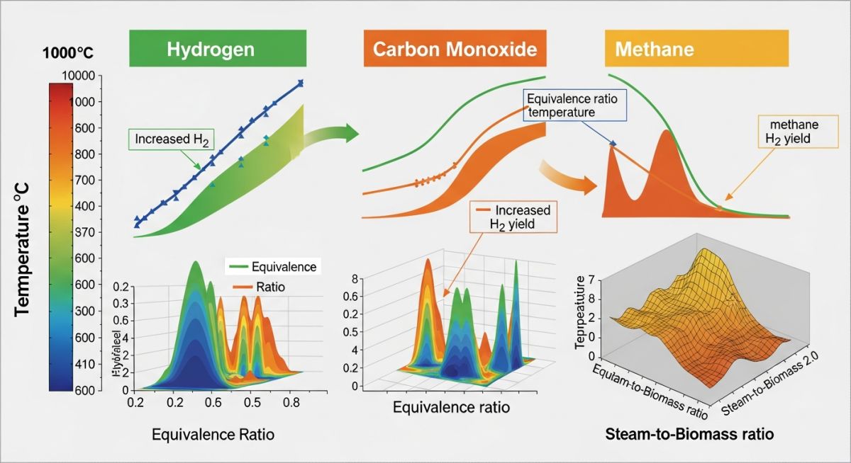
How Bubbling Fluidized Bed Gasifier Variables Impact Hydrodynamics
The table below outlines how key operating variables influence syngas quality, tar yield, and operational risks. These values are based on standard industrial biomass gasification plants operating under ASME PTC 4.7 guidelines.
| Operating Variable | Typical Range | Impact on H2/CO Ratio | Impact on Tar Yield | Primary Operational Risk |
|---|---|---|---|---|
| Bed Temperature | 750°C – 900°C | Increases H2 and CO | Decreases significantly | Ash sintering & agglomeration |
| Equivalence Ratio (ER) | 0.20 – 0.33 | Decreases both H2 and CO | Decreases (combustion) | Dilution with CO2 and N2 |
| Steam-to-Biomass (SBR) | 0.4 – 1.0 | Increases H2/CO ratio | Decreases (reforming) | Bed cooling (thermal loss) |
| Fluidization Velocity (U) | 2 * U_mf – 4 * U_mf | Minimal direct impact | Slight increase (short residence) | Solid elutriation & freeboard bypass |
Technical Mapping & Specifications Matrix
To help process engineers design and integrate these systems, the matrix below maps key physical parameters to their corresponding industry standards and engineering significance.
| Parameter / Entity | Acronym / Symbol | Standard Reference | Engineering Significance |
|---|---|---|---|
| Minimum Fluidization Velocity | U_mf | VDI Heat Atlas | Defines the lower boundary of gas flow to prevent bed stagnation. |
| Process Piping Design | ASME B31.3 | ASME B31.3 | Governs the mechanical integrity of high-temperature syngas piping. |
| Gasifier Performance Test | PTC 4.7 | ASME PTC 4.7 | Provides the standard procedure for calculating cold gas efficiency. |
| Archimedes Number | Ar | Kunii & Levenspiel | Used to characterize the fluidization regime of the bed particles. |
Field Verification Checklist for Gasifier Operators
Before starting up a bubbling fluidized bed gasifier, you must verify several critical parameters on site. This checklist is based on my field experience commissioning commercial-scale gasification plants.
Pre-Start Cold Flow & Mechanical Verification
Verify that the mean particle size (d_p) of your sand or olivine matches the design specification (typically 200 to 500 microns) to prevent premature elutriation or defluidization.
Check all bubble caps or nozzles for blockages. Uneven gas distribution causes dead zones in the bed, leading to localized hot spots and agglomeration.
Calibrate the differential pressure transmitters across the bed. This measurement is your primary tool for monitoring bed height and fluidization quality during operation.
Ensure the nitrogen purge on the biomass feed screw is operational. This prevents hot syngas from back-flowing into the fuel hopper, which is a major fire hazard.
Inspect the internal refractory lining for cracks or spalling, especially around the bed zone where abrasive sand causes high wear.
Field Case Study: Real-World Application
At a 10 MWth biomass gasification plant in Southeast Asia, the operators were using agricultural straw as feedstock and silica sand as the bed material. The gasifier was designed to run at 850°C. However, within 4 hours of startup, the bed differential pressure dropped rapidly, indicating a loss of fluidization.
The bed temperature spiked locally to 920°C, and the syngas Lower Heating Value (LHV) fell to an unusable 3.5 MJ/Nm³. The system had to be shut down, and physical inspection revealed large, glassy agglomerates of fused sand and ash blocking the distributor plate.
My team and I analyzed the fuel ash chemistry and found high levels of potassium (K2O > 15% in ash). We implemented three corrective actions:
- We replaced the silica sand with calcined olivine sand, which has a much higher resistance to alkali reactions.
- We lowered the target operating temperature to 810°C to keep the bed well below the eutectic melting point of the ash.
- We increased the steam-to-biomass ratio (SBR) from 0.2 to 0.6 to compensate for the lower temperature, using steam reforming to maintain hydrogen production.
These changes stabilized the bed. The gasifier ran continuously for over 500 hours without any pressure drops. The syngas LHV increased to 5.2 MJ/Nm³, and tar content in the raw syngas dropped by 45% due to the catalytic activity of the olivine bed material.
Direct Recommendation: Never rely solely on temperature transmitters to detect bed agglomeration. Always monitor the standard deviation of the bed differential pressure. A sudden decrease in pressure fluctuations is the earliest warning sign of bed defluidization.
Frequently Asked Engineering Questions
What is the ideal equivalence ratio (ER) for a bubbling fluidized bed gasifier?
How does bed material selection prevent agglomeration?
Why is steam injection preferred over air-only gasification?
What is the role of the Archimedes number in gasifier hydrodynamics?
How does freeboard height affect syngas quality?
What piping standards govern the design of gasifier feed and syngas lines?
===FAQ_BLOCK===

Complete Course on
Piping Engineering
Check Now
Key Features
- 125+ Hours Content
- 500+ Recorded Lectures
- 20+ Years Exp.
- Lifetime Access
Coverage
- Codes & Standards
- Layouts & Design
- Material Eng.
- Stress Analysis