Bulkhead Fittings: A Comprehensive Guide to Leak-Proof Tank Connections
In my 20 years of commissioning chemical process plants and high-pressure piping systems, I have seen minor connection points cause major plant shutdowns. Among these, tank penetration points are notoriously vulnerable. When you need to transition a piping run through a thin-walled vessel, a standard threaded connection simply will not hold up. This is where bulkhead fittings become your primary line of defense.
These components act as structural bridges, clamping onto the vessel wall from both sides to distribute mechanical loads while maintaining a gas-tight or liquid-tight seal. Throughout my career, I have selected and installed thousands of these connectors across diverse applications, from highly corrosive acid storage tanks to high-purity pharmaceutical vessels.
Key Engineering Takeaways
- Understand the mechanical clamping mechanics that prevent vessel wall deformation.
- Master the torque calculations required to seat gaskets without crushing them.
- Select the correct material pairings to avoid galvanic corrosion and chemical degradation.
- Implement field-proven installation steps to eliminate common leak paths.
Why Bulkhead Fittings Fail in Industrial Systems
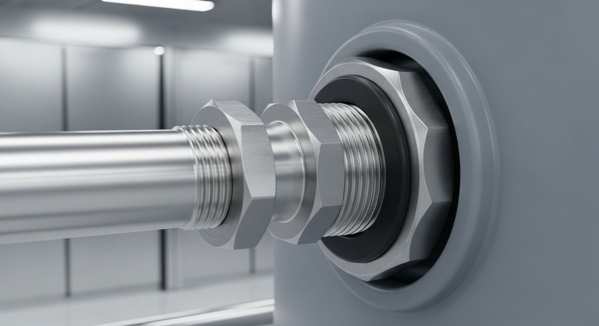
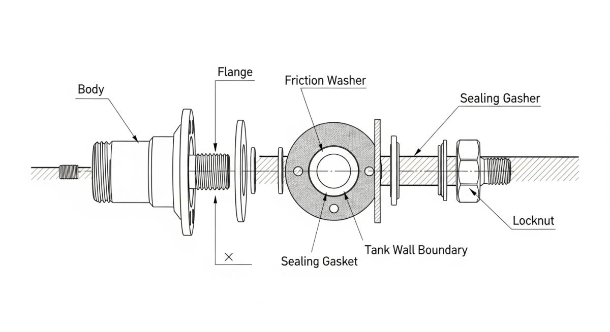
To design a truly reliable tank connection, we must first analyze the mechanical forces at play. A bulkhead fitting consists of a body with an integrated flange, a gasket, a locknut, and sometimes a friction washer. When you tighten the locknut, you generate an axial clamping force that compresses the gasket against the vessel wall.
However, in my field investigations, I often find that installers treat these fittings like standard pipe joints, leading to premature failures. Let us look at the primary mechanical stress calculations that govern these connections.
Calculating Gasket Seating Stress
To achieve a leak-proof seal, the clamping force must generate a minimum gasket seating stress. This stress must overcome the internal fluid pressure without exceeding the maximum allowable compressive stress of the gasket material. The required clamping force (F) can be calculated using the following engineering formula:
Where:
S_g = Minimum gasket seating stress (MPa or PSI) based on ASME Section VIII Division 1, Appendix 2
A_g = Contact area of the gasket (mm² or in²)
A_g = (pi / 4) * (D_outer² – D_inner²)
Where D_outer is the outer diameter of the gasket, and D_inner is the inner diameter.
If you are working with a 2-inch stainless steel bulkhead fitting using a PTFE gasket, the minimum seating stress (S_g) is typically around 20 MPa (2900 PSI). If the installer fails to apply the correct torque to the locknut, the actual seating stress will fall below this threshold, allowing the process fluid to bypass the gasket under hydrostatic pressure.
When installing metallic bulkhead fittings on plastic tanks (such as HDPE or PP), you must account for material creep. Over time, the plastic tank wall will slowly deform under the constant clamping pressure of a metallic fitting. This reduces the active clamping force and leads to leaks. Always use a backing flange or a load-distribution plate in these scenarios to spread the mechanical load over a wider surface area.
Thermal Expansion and Mechanical Piping Loads
Another common failure point is the transfer of piping loads directly to the bulkhead connection. According to ASME B31.3 Process Piping guidelines, piping systems must be supported such that they do not impose excessive shear or bending moments on vessel nozzles.
Because a bulkhead fitting is clamped directly to the relatively thin wall of a tank, any thermal expansion or vibration from the connected piping will act as a lever arm, flexing the tank wall and breaking the gasket seal. I always insist on installing flexible expansion joints or structural pipe supports immediately adjacent to any bulkhead connection to isolate it from these dynamic forces.
The following data tables provide the exact torque limits and material compatibility matrices that I use during the design phase of industrial fluid handling systems. These values ensure compliance with standard piping practices and prevent mechanical damage during assembly.
Table 1: Recommended Tightening Torque by Material and Size
| Nominal Size (NPT/BSP) | PVC / CPVC Torque (Nm) | PP / PVDF Torque (Nm) | 316 Stainless Steel Torque (Nm) | Recommended Gasket Material |
|---|---|---|---|---|
| 1/2″ | 10 – 12 | 8 – 10 | 35 – 40 | EPDM / FKM |
| 1″ | 20 – 25 | 15 – 18 | 65 – 75 | EPDM / PTFE |
| 2″ | 45 – 50 | 35 – 40 | 140 – 160 | PTFE / Envelope |
| 3″ | 70 – 80 | 55 – 65 | 220 – 250 | Spiral Wound / PTFE |
Table 2: Technical Mapping & Specifications Matrix
| Technical Entity | Acronym | Physical Parameter | Standard Reference |
|---|---|---|---|
| National Pipe Thread | NPT | Tapered Thread Angle (60 degrees) | ASME B1.20.1 |
| British Standard Pipe | BSP | Parallel/Tapered Thread Angle (55 degrees) | ISO 228 / ISO 7 |
| Polytetrafluoroethylene | PTFE | Chemical Resistance & Gasket Hardness | ASTM D4894 |
| Ethylene Propylene Diene Monomer | EPDM | Elastomeric Recovery & Durometer | ASTM D1418 |
How to Install Bulkhead Fittings Without Leaks
Over the years, I have developed a strict field installation protocol. If my crew skips even one of these steps, the probability of a joint failing during hydrotesting increases exponentially. I highly recommend printing this checklist and keeping it in your field manual.
Site Verification Checklist
-
Hole Cut Quality: Ensure the hole is cut using a high-quality hole saw. Deburr both the inner and outer edges completely. Any remaining plastic or metal shavings will prevent the gasket from seating flat.
-
Gasket Placement: Place the primary sealing gasket on the flange side of the bulkhead body (inside the tank). The locknut side (outside the tank) should receive the friction washer to prevent the nut from tearing the gasket during tightening.
-
Thread Inspection: Inspect the external threads of the bulkhead body for any nicks or flat spots. For plastic fittings, never use metal wrenches directly on the plastic threads; use a strap wrench instead.
-
Calibrated Torque: Use a calibrated torque wrench to tighten the locknut to the specified value in Table 1. Do not rely on “hand-tight plus a quarter turn” for industrial process lines.
-
Hydrostatic Testing: Perform a low-pressure static head test or a pneumatic bubble test in accordance with API 650 before filling the vessel to capacity.
Field Case Study: Real-World Application
The Problem: Recurring Failures in a Sulfuric Acid Storage Tank
At a chemical processing facility in Texas, a 10,000-gallon HDPE storage tank containing 98% concentrated sulfuric acid experienced recurring leaks at its lower drain connection. The original installation utilized a standard PVC bulkhead fitting with an EPDM gasket.
Within three months of operation, the EPDM gasket degraded due to chemical attack, and the PVC threads began to shear under the weight of the unsupported 3-inch drain piping. The resulting leak forced an emergency neutralization process and cost the facility over 45,000 in lost production time.
The Outcome: Engineered Redesign and Material Upgrade
I was called in to audit the system. We immediately replaced the PVC fitting with a heavy-duty PVDF (Polyvinylidene Fluoride) bulkhead fitting, which offers superior chemical resistance to concentrated sulfuric acid. We replaced the degraded EPDM gasket with a virgin PTFE envelope gasket.
To address the mechanical load, we installed a spring-loaded pipe hanger to support the drain line, isolating the bulkhead from the piping weight. Finally, we added a 316 stainless steel backing plate to distribute the clamping force evenly across the HDPE tank wall. During the subsequent hydrotest and throughout the following two years of continuous operation, the connection remained completely dry.
This case highlights why you must evaluate both chemical compatibility and mechanical piping loads simultaneously. Simply replacing the gasket with a better material would not have solved the thread shear issue caused by the unsupported piping.
Frequently Asked Engineering Questions
What is the difference between a bulkhead fitting and a tank flange?
Which side of the tank wall should the gasket be placed on?
Can I use thread sealant on the external threads of a bulkhead fitting?
How do I prevent galvanic corrosion when using metallic fittings on metal tanks?
What is the maximum pressure rating for a standard bulkhead fitting?
How do I handle bulkhead installations on curved tank walls?
Complete Course on
Piping Engineering
Check Now
Key Features
- 125+ Hours Content
- 500+ Recorded Lectures
- 20+ Years Exp.
- Lifetime Access
Coverage
- Codes & Standards
- Layouts & Design
- Material Eng.
- Stress Analysis