What is a Distillation Column? Working Principles and Types
In my 20-plus years of commissioning and troubleshooting petrochemical plants, I have yet to find a piece of equipment as central to chemical processing as the distillation column. Often referred to as the beating heart of a refinery, these massive vertical towers are responsible for separating complex mixtures into high-purity products. Whether you are splitting crude oil into transportation fuels or separating high-purity chemical intermediates, understanding the mechanical and thermodynamic design of these columns is a fundamental requirement for any piping or process engineer.
When I first stepped onto a construction site in the late 1990s, the sheer scale of a 60-meter-tall fractionator was intimidating. But once you look past the external piping, insulation, and structural platforms, you realize that a distillation column is a beautifully balanced thermodynamic system. It relies on the simple physical reality that different liquids boil at different temperatures. By managing the counter-current flow of rising vapor and falling liquid, we can achieve incredibly precise separations.
Key Engineering Takeaways
- Thermodynamic Foundation: Separation relies entirely on relative volatility and vapor-liquid equilibrium (VLE).
- Mechanical Integrity: Columns must be designed to withstand high wind loads, seismic forces, and internal pressure/vacuum conditions per ASME Section VIII.
- Hydraulic Limits: Operating window limits such as weeping, entrainment, and flooding dictate the column’s maximum and minimum throughput.
- Internal Selection: The choice between trays and packings directly impacts pressure drop, liquid holdup, and separation efficiency.
Complete Course on
Piping Engineering
Check Now
Key Features
- 125+ Hours Content
- 500+ Recorded Lectures
- 20+ Years Exp.
- Lifetime Access
Coverage
- Codes & Standards
- Layouts & Design
- Material Eng.
- Stress Analysis
How Does a Distillation Column Actually Work?
Vapor-Liquid Equilibrium Mechanics: The separation process inside a distillation column relies on continuous counter-current contact where rising vapor strips volatile components from descending liquid. This thermal separation is governed by Raoult’s Law and Dalton’s Law, ensuring high-purity overhead and bottom product streams.
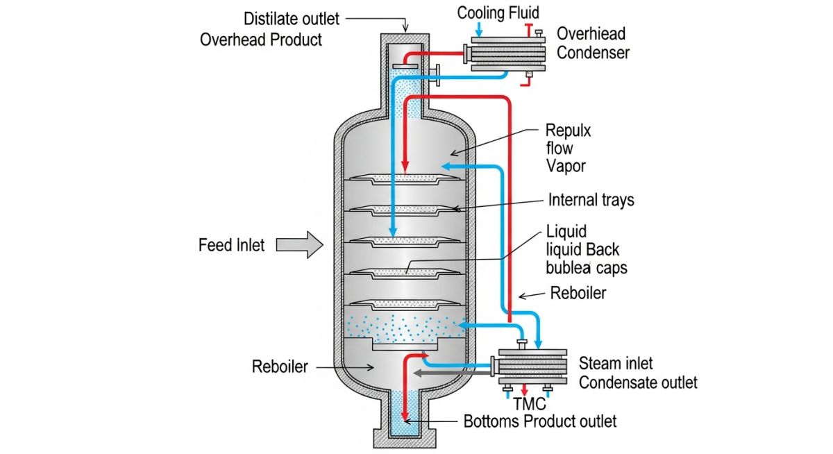
To understand the internal mechanics, let us trace the path of the process fluid. The feed stream enters the column at an intermediate point called the feed tray. This feed is typically a mixture of two or more components. The section of the column above the feed point is known as the rectifying (or enriching) section, where the concentration of the more volatile component is increased. The section below the feed point is the stripping section, where the volatile components are stripped from the descending liquid.
Heat is introduced at the bottom of the column via a reboiler. This heat vaporizes a portion of the liquid, which then begins its journey upward through the column internals. At the top of the column, vapor is collected, condensed in an overhead condenser, and accumulated in a reflux drum. A portion of this condensed liquid is returned to the top of the column as reflux, while the remainder is drawn off as the distillate product.
Core Design Calculations and Formulas
As piping and vessel engineers, we must collaborate closely with process engineers to translate thermodynamic requirements into physical steel. The sizing of a distillation column is heavily influenced by two primary calculations: relative volatility and the column capacity parameter.
1. Relative Volatility (alpha): This parameter measures the ease of separation between two components. It is defined as the ratio of the vapor-liquid distribution coefficients (K-values) of the light component (i) to the heavy component (j):
Where:
• y_i, y_j = mole fractions in the vapor phase.
• x_i, x_j = mole fractions in the liquid phase.
If alpha is close to 1.0, separation is extremely difficult, requiring a very tall column with many trays and a high reflux ratio.
2. Column Diameter and Vapor Velocity (Souders-Brown Equation): To prevent liquid entrainment (where rising vapor carries liquid droplets up to the next tray), we calculate the maximum allowable vapor velocity using the Souders-Brown correlation:
Where:
• V_max = Maximum allowable vapor velocity (ft/s or m/s).
• C_sb = Capacity parameter, which depends on tray spacing and liquid surface tension.
• rho_l = Density of the liquid phase.
• rho_v = Density of the vapor phase.
Once V_max is established, the cross-sectional area and subsequent internal diameter of the column shell can be calculated based on the design vapor volumetric flow rate.
Selecting the Right Distillation Column Internals
Column Internals Selection: Choosing between trays and structured packings inside a distillation column depends on operating pressure, allowable pressure drop, and liquid-to-vapor loading ratios. Proper selection ensures optimal mass transfer efficiency while preventing hydraulic failures like entrainment or dry-out.
In my practice, the decision to use trays versus packing is one of the most critical choices in the design phase. Trays are generally preferred for high-pressure applications, systems with high liquid rates, or services prone to fouling. Packings, on the other hand, offer exceptionally low pressure drop, making them the industry standard for vacuum distillation columns where minimizing bottom temperature is necessary to prevent thermal degradation of the product.
Trays operate by forcing vapor to bubble through a pool of liquid maintained on each tray deck. The three most common tray types are:
- Sieve Trays: Simple perforated plates. They are inexpensive but have limited flexibility (low turndown ratio) and can weep at low vapor rates.
- Valve Trays: Feature liftable caps over the perforations. The valves open and close dynamically with vapor flow, offering excellent turndown capability.
- Bubble Cap Trays: Feature fixed caps over risers. These are used for very low liquid rates where maintaining a liquid seal is critical, though they are expensive and heavy.
The table below outlines the key performance characteristics of various column internals. This data is compiled from field performance records and standard design guidelines under API standards.
| Internal Type | Pressure Drop | Turndown Ratio | Fouling Resistance | Relative Cost | Primary Application |
|---|---|---|---|---|---|
| Sieve Trays | Moderate (50-80 mmH2O) | 2:1 | Fair | Low (1.0) | Standard chemical separations |
| Valve Trays | Moderate (60-90 mmH2O) | 4:1 to 5:1 | Good | Medium (1.3) | Refinery fractionators |
| Bubble Cap Trays | High (80-120 mmH2O) | 8:1 | Poor | High (2.0) | Low liquid load / batch systems |
| Random Packing | Low (15-30 mmH2O) | 3:1 | Moderate | Medium (1.2) | Corrosive / acid gas absorption |
| Structured Packing | Very Low (5-15 mmH2O) | 5:1 | Very Poor | Very High (2.5) | Vacuum distillation / isomer splitters |
This matrix maps the critical auxiliary components of a distillation system, their primary design codes, and typical materials of construction (MOC) used in modern petrochemical facilities.
| Component | Primary Function | Design Code / Standard | Typical Materials (MOC) | Key Design Parameter |
|---|---|---|---|---|
| Column Shell | Pressure containment and structural support | ASME Sec VIII Div 1 | ASTM A516 Gr 70 / 316L SS | Wind and seismic load resistance |
| Reboiler | Provides heat input to vaporize bottom liquid | TEMA R / ASME Sec VIII | Carbon Steel / Duplex SS | Heat flux and fouling factor |
| Overhead Condenser | Condenses overhead vapor to liquid | TEMA R / API 660 | Admiralty Brass / Titanium | Log Mean Temperature Difference (LMTD) |
| Reflux Drum | Accumulates condensed liquid for reflux/product | ASME Sec VIII Div 1 | ASTM A106-B / Carbon Steel | Liquid residence time (typically 5-10 mins) |
| Demister Pad | Removes entrained liquid droplets from vapor | Manufacturer Standard | 304 SS / Monel mesh | Vapor velocity and pressure drop |
Pre-Commissioning Inspection Protocol: Before introducing hydrocarbons into a distillation column, a rigorous mechanical and hydraulic verification must be performed to confirm internal alignment and seal integrity. This field protocol ensures all tray levelness, packing density, and nozzle orientations comply with the approved engineering drawings.
During my career, I have witnessed several costly startups fail simply because a minor internal component was installed incorrectly. A single loose tray panel or an unsealed downcomer can completely bypass the liquid flow, rendering the column useless. Use this checklist during your next turnaround or new-build inspection.
Mechanical & Hydraulic Verification Checklist
-
Tray Levelness Verification: Ensure all trays are level within the tolerance specified by the manufacturer (typically +/- 3 mm across the column diameter). Out-of-level trays cause maldistribution of liquid.
-
Downcomer Clearance Check: Measure and record the downcomer clearance (the gap between the bottom of the downcomer and the tray below). Verify it matches the process design datasheet to prevent premature flooding.
-
Weir Height Alignment: Verify that the outlet weir height is uniform and matches the drawings. This controls the liquid holdup on each tray.
-
Packing Bed Density & Leveling: For packed columns, verify that random packing is poured evenly without voids, and structured packing elements are tightly fitted with no bypass gaps at the column wall.
-
Liquid Distributor Leveling: Ensure the gravity-fed liquid distributors above packed beds are perfectly level and all orifices or drip tubes are free of debris.
-
Manway Gasket Integrity: Confirm that all internal and external manway gaskets are replaced with new, specified materials and torqued using the correct cross-pattern method.
Field Case Study: Real-World Application
The Problem: Severe Pressure Drop and Loss of Separation
In 2018, I was called to a petrochemical plant in Southeast Asia. Their primary C3 splitter—a massive distillation column with 120 valve trays—was experiencing severe pressure drop spikes. The column was designed to produce polymer-grade propylene (99.5% purity), but the overhead purity had dropped to less than 95%.
The field operators reported that any attempt to increase the reboiler steam rate resulted in immediate liquid carryover into the overhead condenser, indicating a classic case of column flooding. The plant was forced to run at 60% design capacity to maintain even basic operation.
The Diagnostic and Outcome
We initiated a gamma scan of the column while it was operating. The gamma scan profile revealed a massive liquid accumulation (liquid hold-up) starting around Tray 45 and extending up to Tray 52. This confirmed localized downcomer backup flooding.
During the subsequent emergency shutdown, we opened the column manways for inspection. We discovered that several valve caps on Tray 45 had detached and lodged themselves inside the downcomer inlet of Tray 46. This mechanical blockage restricted the downward flow of liquid, causing the liquid to back up onto the trays above.
We cleared the debris, replaced the damaged trays with heavy-duty caged valve trays to prevent future cap loss, and verified the downcomer clearances. Upon startup, the column returned to 100% design capacity with a stable pressure drop and achieved the required 99.5% propylene purity.
My Direct Recommendation: Always include a robust mechanical locking mechanism or use caged/fixed valves in high-vibration or high-velocity zones of the column. Standard push-out valves can easily pop out of their seats during minor pressure surges, leading to catastrophic hydraulic blockages downstream.
Frequently Asked Engineering Questions
What is the difference between a trayed and packed distillation column?
How does reflux ratio affect distillation column design?
What causes weeping in a distillation column?
How do you prevent flooding in a distillation column?
What is the purpose of a reboiler in a distillation column?
Which ASME codes govern distillation column design?
===