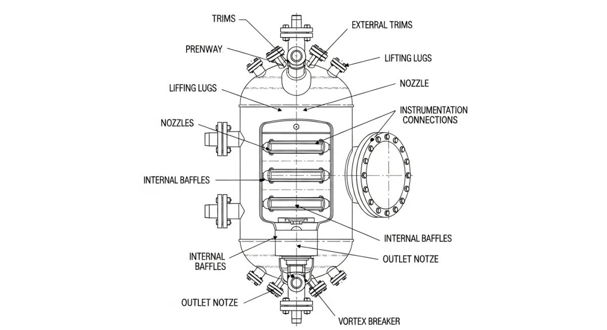
What are Vessel Trims? Examples and Characteristics of Pressure Vessel Trims
I still remember a shutdown job at a refinery where a junior engineer told me, “Sir, trims are just small attachments, right?” That one misunderstanding cost us two days because the procurement team missed a vortex breaker inside the vessel.
In the EPC world, vessel trims are not optional accessories. They directly influence process performance, safety, maintenance, and even instrumentation accuracy. And yet, I keep seeing confusion between trims, fittings, and attachments even among experienced engineers.
In this guide, I’ll break down vessel trims the way we actually handle them in the field — with real examples, mistakes, and sharp engineering logic.
- Vessel trims include internal and external functional components attached to pressure vessels.
- They are different from structural supports and are process-driven elements.
- Examples include nozzles, manways, baffles, demisters, vortex breakers.
- Wrong understanding of trims leads to instrument errors, flow issues, and costly rework.
- In EPC projects, trims must be clearly defined in datasheets and GA drawings.
Vessel trims are functional components attached to pressure vessels that support process operation, safety, and maintenance. These include internal elements like baffles and demisters, and external components like nozzles and manways. Unlike structural supports, trims directly impact fluid flow, separation efficiency, and instrumentation performance.
Interactive Engineering Quiz
Technical Deep-Dive: Vessel Trims (From Datasheet to Field Reality)
In my experience, confusion around vessel trims starts at the datasheet stage itself. Teams mix up trims with attachments, and that mistake travels all the way to procurement and installation. On-site, that turns into rework, delays, and sometimes unsafe operation.
Let me break this down exactly the way we handle it in EPC design reviews and field execution.
What Exactly Qualifies as a Vessel Trim?
A vessel trim is any component—internal or external—that directly interacts with the process. If it affects flow pattern, separation efficiency, or instrumentation performance, I classify it as a trim.
Do not assume all attachments are trims. Supports like skirts and saddles are structural. But a nozzle with a dip pipe? That becomes a trim because it directly alters process behavior. This distinction is where many engineers slip.
Classification of Vessel Trims (Engineering View)
- Internal Trims – Installed inside the vessel to control flow or separation
- External Trims – Mounted outside but connected to process fluid or instruments
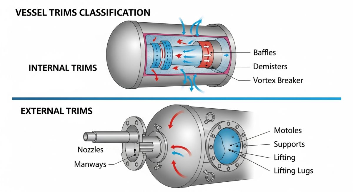
Detailed Breakdown of Vessel Trim Functions
In EPC execution, we don’t just list trims — we define their functional intent. That is what drives correct sizing, orientation, and fabrication.
| Trim Type | Function | Field Impact | Code Reference |
|---|---|---|---|
| Nozzle Trims (Dip Pipes / Spargers) | Control flow direction and entry | Avoid turbulence and vortex formation | ASME Section VIII Div 1 |
| Demisters / Mist Eliminators | Remove liquid droplets from gas | Improves separation efficiency | HEI / Vendor Standards |
| Baffles / Flow Breakers | Control flow pattern | Prevents channeling or dead zones | Project Specifications |
| Vortex Breakers | Prevent vortex at outlet | Avoid gas entrainment | Hydraulic Design Guidelines |
| Level Gauge Nozzle Trims | Ensure accurate reading | Wrong orientation leads to false level | ISA Standards |
How Vessel Trims Are Defined in EPC Documents
On a real project, I always ensure trims are locked in across three documents:
- Vessel Datasheet – Functional requirement
- GA Drawing – Relative positioning and orientation
- Fabrication Drawing – Exact dimensions and weld details
If trims are only mentioned in datasheets but not shown in GA drawings, they will get missed during fabrication. I have seen this happen more times than I would like to admit.
Field Case Study: Real-World Application
During commissioning of a separator vessel in a refinery unit, we observed unstable level readings. The control valve kept oscillating, and operations reported inconsistent liquid draw-off.
Action & Technical Analysis
I inspected the vessel internals along with the instrumentation team. The root issue was with the level gauge nozzle trim.
- Nozzle was directly exposed to turbulent inlet flow
- No calming arrangement or dip pipe was provided
- Vortex formation caused fluctuating readings
We redesigned the trim with:
- Extended dip pipe away from turbulence zone
- Added perforations for pressure equalization
- Adjusted orientation based on flow pattern
Level fluctuation reduced by ~80%. Control valve stabilized, and the vessel achieved steady-state operation within hours instead of repeated trips.
Field Lesson Learned: Never treat nozzle trims as minor details. If the flow physics is ignored, the instrument will lie — and the plant will suffer.
Executive FAQ: Vessel Trims
What is the difference between vessel trims and attachments?
Are nozzles always considered vessel trims?
Why are internal trims critical for separators?
Where are vessel trims specified in project documents?
What happens if a vortex breaker is missing?
How do you validate vessel trim design before fabrication?
Complete Course on
Piping Engineering
Check Now
Key Features
- 125+ Hours Content
- 500+ Recorded Lectures
- 20+ Years Exp.
- Lifetime Access
Coverage
- Codes & Standards
- Layouts & Design
- Material Eng.
- Stress Analysis
