Chemical Injection Quill: Design, Types, and Engineering Standards 2026
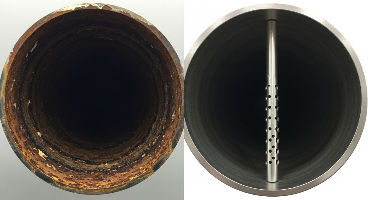
Imagine a multi-million dollar offshore pipeline slowly being eaten away by localized corrosion because your inhibitor is simply running along the bottom of the pipe instead of atomizing into the flow. This “wall-streaming” effect is the silent killer of process integrity. A Chemical Injection Quill is the precision instrument engineered to solve this, ensuring chemicals are delivered into the center of the flow stream for immediate dispersion.
In this guide, we dive deep into the mechanical configurations and ASME design requirements that separate a standard pipe nipple from a high-performance injection system.
Key Takeaways
- Understanding why center-stream injection is mandatory for ASME B31.3 compliance.
- Differentiating between retractable and fixed configurations for maintenance planning.
- Selection of MOC based on fluid velocity and chemical compatibility.
What is a Chemical Injection Quill?
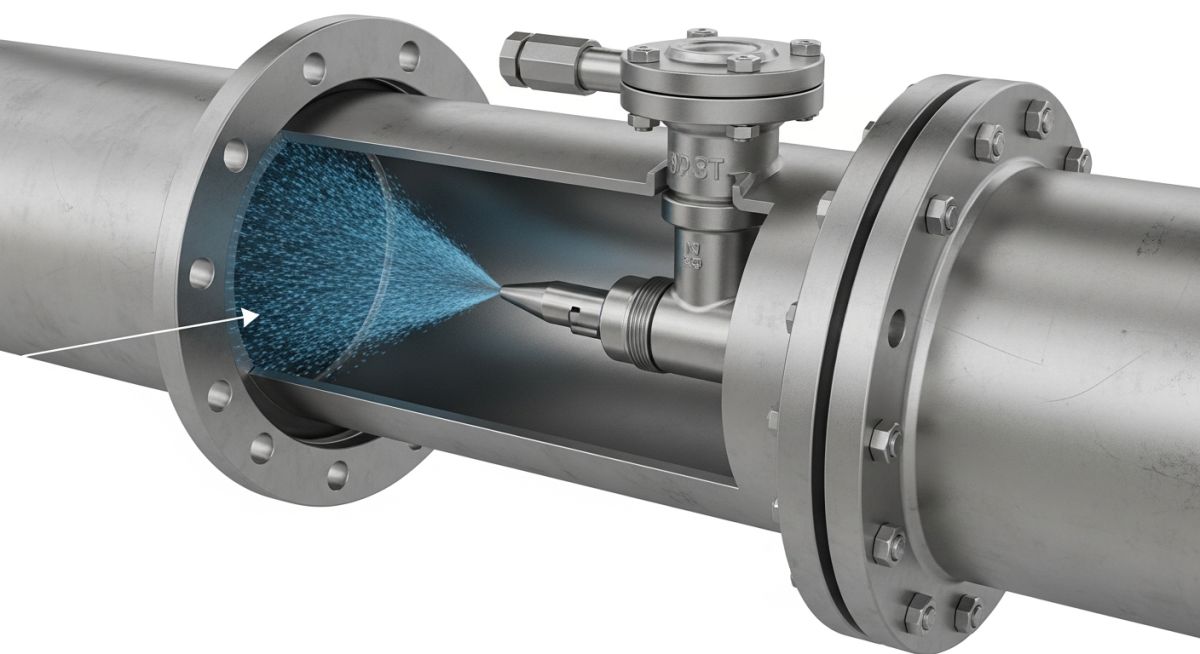
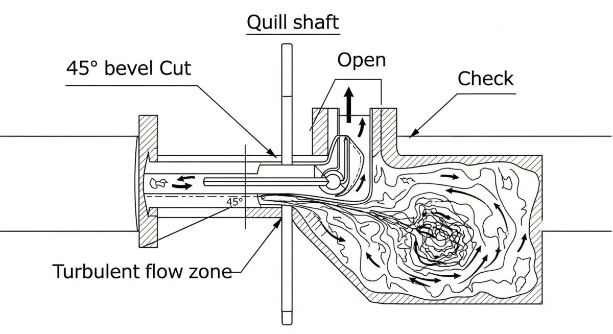
A Chemical Injection Quill is a specialized piping component used to introduce chemicals into a process stream. It extends into the center of the pipe to ensure uniform mixing and prevent concentrated chemicals from damaging the pipe wall. Most quills feature a 45-degree bevel and an integral check valve to prevent backflow.
“In my 20 years of piping design, the most common failure I see isn’t the quill itself, but the lack of a vortex shedding calculation. If your quill length isn’t tuned to the flow velocity, vibration will snap it off in weeks.”
– Atul Singla, Founder of EPCLand
Complete Course on
Piping Engineering
Check Now
Key Features
- 125+ Hours Content
- 500+ Recorded Lectures
- 20+ Years Exp.
- Lifetime Access
Coverage
- Codes & Standards
- Layouts & Design
- Material Eng.
- Stress Analysis
1. Why is a 45-degree bevel cut used at the tip of a Chemical Injection Quill?
Critical Applications of the Chemical Injection Quill
In modern process engineering, the Chemical Injection Quill serves as the primary interface between high-pressure dosing systems and the main process pipeline. Without this component, chemicals such as corrosion inhibitors, scale inhibitors, and biocides would fail to mix effectively, leading to localized “hot spots” of chemical concentration and accelerated pipe wall thinning.
The application of these quills is particularly critical in the oil and gas sector, where corrosion management is a multi-billion dollar priority. By projecting the chemical into the center-third of the pipe, the quill leverages the maximum velocity profile of the fluid to achieve immediate dispersion. According to the technical guidelines provided by NACE International (now AMPP), proper injection methodology is the single most effective way to extend the lifespan of carbon steel assets in sour service.
Primary Types of Chemical Injection Quill Systems
Selecting the right architecture for your Chemical Injection Quill depends entirely on your operational maintenance philosophy and pressure ratings. Engineers typically classify these into two distinct categories:
1. Fixed Injection Quills
Fixed quills are the industry standard for low-risk, steady-state operations. They are permanently installed via a NPT thread or a flanged connection. While cost-effective, their primary drawback is that the process line must be depressurized and drained before the quill can be inspected or replaced. They are ideal for non-corrosive injection fluids where the risk of nozzle plugging is minimal.
2. Retractable Injection Quills
For critical infrastructure where downtime is not an option, the Retractable Chemical Injection Quill is mandatory. These assemblies utilize a “corporation stop” or a specialized packing gland and safety chain system. This allows the operator to isolate the quill from the main process flow using a ball valve and withdraw it for cleaning while the pipeline remains under pressure. This is a standard requirement in refinery overhead systems where wash water injection must be continuous.
Standard Chemical Injection Quill Configurations
The configuration of a quill is not merely aesthetic; it is governed by fluid mechanics. The most common configuration is the 45-degree bevel cut. This design is installed with the opening facing away from the flow, creating a localized low-pressure zone (the Bernoulli effect) that “sucks” the chemical into the turbulent wake of the quill, ensuring rapid homogenization.
Engineering Guide: Designing a Chemical Injection Quill
Designers must ensure that every Chemical Injection Quill complies with ASME B31.3 (Process Piping) standards. The design process begins with determining the “Insertion Length.” As a rule of thumb, the tip of the quill should reside at the center-line of the pipe, or at least within the middle third of the diameter.
Design Calculation & Velocity Ratios
The engineering of a Chemical Injection Quill goes beyond simple geometry. Designers must calculate the Vortex Shedding Frequency to ensure it does not coincide with the natural frequency of the quill. If the flow-induced vibration (FIV) matches the mechanical resonance, the quill will suffer fatigue failure. Per ASME PTC 19.3 TW, which is the gold standard for thermowell and quill stress analysis, the velocity ratio must be kept within safe limits to prevent mechanical snapping.
Material of Construction (MOC)
Material selection is dictated by the ASME B31.3 fluid service category. While 316L Stainless Steel is the baseline, highly aggressive chemicals like concentrated sulfuric acid or sodium hypochlorite require exotic alloys. Common choices include Hastelloy C276 for extreme corrosion resistance or Inconel 625 for high-temperature applications. It is vital to ensure that the quill material is cathodic to the pipeline to prevent the quill from becoming a sacrificial anode.
The Working Principle of a Chemical Injection Quill
The Chemical Injection Quill operates on the principle of differential pressure and turbulent diffusion. As the process fluid moves past the quill, it creates a “Von Karman vortex street” in the wake of the stem. The chemical is injected into this high-turbulence zone, which provides the kinetic energy required for rapid mixing. Without the quill, the chemical would travel in a “laminar streak” along the pipe wall, leading to under-deposit corrosion and inefficient chemical utilization.
Essential Components of a Chemical Injection Quill Assembly
| Component | Technical Function | Standard Requirement |
|---|---|---|
| Integral Check Valve | Prevents process fluid backflow into the dosing line. | API 594 / API 6D |
| Quill Stem | The delivery tube extending into the flow stream. | ASME B31.3 |
| Safety Chain/Cable | Required for retractable models to prevent accidental ejection. | OSHA / Engineering Best Practice |
| Isolation Valve | Allows maintenance without shutting down the main line. | API 608 (Ball Valves) |
Engineering Selection Criteria for a Chemical Injection Quill
When specifying a Chemical Injection Quill, the engineer must evaluate the Reynolds Number of the process fluid. For gas injection into liquid, a nozzle-tipped quill (atomizer) is preferred. For liquid-into-liquid, a standard 45-degree bevel is usually sufficient. Further guidance on piping components can be found on the official ASME B31.3 Standard Page.
EPCLand YouTube Channel
2,500+ Videos • Daily Updates
Chemical Injection Quill: Velocity & Ratio Calculator
Estimate the injection velocity and check if your quill tip is positioned for optimal dispersion according to standard flow ratios.
Technical Validation
Note: This tool provides a geometric validation. Always perform a Vortex Shedding Calculation per ASME PTC 19.3 TW for final engineering approval.
Don't miss this video related to Chemical Injection
Summary: Master Piping Engineering with our complete 125+ hour Certification Course: ......
Case Study: Reducing Pipeline Failure in Sour Gas Service
The Challenge
An offshore production platform in the North Sea experienced localized 6 o'clock corrosion in a 12-inch carbon steel export line. Despite dosing 15 liters/day of film-forming corrosion inhibitor, ultrasonic testing (UT) showed a metal loss rate of 1.5mm/year. Investigation revealed the chemical was being injected via a simple wall-mounted nipple, causing it to pool at the bottom of the pipe without ever reaching the top of the internal circumference.
The Solution
The engineering team replaced the nipple with a Retractable Chemical Injection Quill featuring a 4-inch insertion length and a 45-degree bevel. The assembly included an integral Hastelloy C276 spring-loaded check valve to prevent the H2S-rich gas from entering the dosing skid.
Technical Results:
- Mixing Efficiency: Center-stream injection improved chemical distribution by 85%.
- Asset Life: Corrosion rates dropped from 1.5mm/year to <0.05mm/year.
- ROI: The Chemical Injection Quill upgrade paid for itself in 14 days by reducing inhibitor wastage.
Expert Insights: Lessons from 20 years in the field
Avoid "Cold-Finger" Effects: In high-temperature gas lines, injecting a cold liquid through a Chemical Injection Quill can cause thermal shock at the tip. Always specify a thermal sleeve or heavy-wall quill stem for applications exceeding 200°C to prevent stress cracking.
The 45-Degree Orientation Rule: The most common field error is installing the bevel facing the flow. To utilize the Bernoulli Effect for proper atomization, the opening must face downstream, away from the incoming fluid.
Vortex Shedding is Non-Negotiable: For gas velocities exceeding 15 m/s, never install a quill without a resonance check. A snapped Chemical Injection Quill inside a pipeline can travel downstream and destroy expensive turbine blades or control valves.
References & Standards
The design and maintenance of injection systems are governed by the following global engineering standards:
Frequently Asked Questions: Chemical Injection Quill Engineering
What is the main purpose of a Chemical Injection Quill?
Which material is best for an injection quill in sour service?
How do I prevent a quill from snapping due to high flow?
Is a retractable quill worth the extra cost over a fixed one?
What happens if the internal check valve fails?
Why is the 45-degree bevel cut angled away from the flow?

Related posts:
![Outdoor pipeline block valve station with large isolation valves and actuators.]()
What are Pipeline Block Valves and How to Design Stations
![3D CAD model of an industrial process plant showing equipment clearances and access platforms.]()
A Guide to Plant Clearances and Access Requirements
![Engineering technical bid evaluation spreadsheet comparing vendor specifications and compliance metrics.]()
How to Master Technical Bid Evaluation for Complex Engineering Procurement
![Large-diameter steel pipes with protective blue anti-corrosive epoxy coating stacked in an industrial facility.]()
Protecting Steel Pipes with Anti-Corrosive Steel Pipe Coatings
![3D CAD model of industrial piping showing stress intensification factor heatmaps at elbows and tees.]()
Why Stress Intensification Factor in Piping Dictates Fatigue Life
![A collection of different industrial pipe flange gaskets on a workbench]()
How to Select the Best Pipe Flange Gaskets for Piping Systems