Pipe End Cap Fittings: Comprehensive Guide on Pipe Caps vs Plugs vs Blind Flanges
Pipe End Cap Fittings serve as the primary structural closure for piping systems, designed to block the flow and provide a permanent or temporary seal at the end of a line. In 2026, understanding the metallurgical and geometric nuances of these fittings is critical for maintaining system integrity in high-pressure environments.
Quick Answer: What are Pipe End Cap Fittings?
Pipe End Cap Fittings are protective piping components used to terminate a flow line. Unlike plugs that fit inside a pipe or blind flanges that bolt to a flange, caps fit over the outside of the pipe and are typically joined via buttweld, socket weld, or threads.
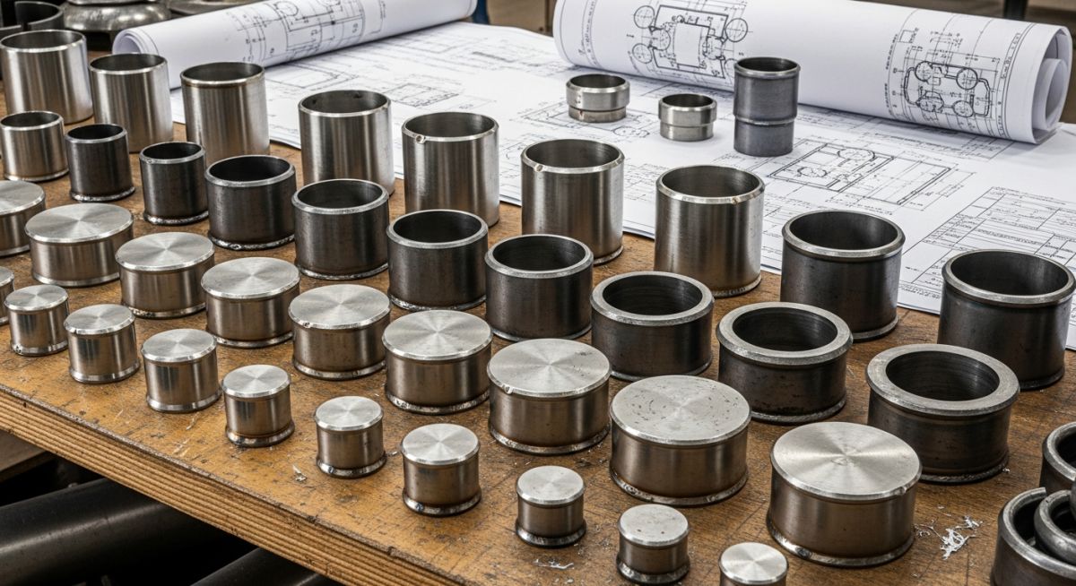
Table of Contents
- What is a Pipe End Cap?
- Primary Materials for Pipe End Cap Fittings
- Engineering Shapes of Pipe End Cap Fittings
- ASME and API Pipe Cap Standards
- Industrial Types of Pipe End Cap Fittings
- Technical Specification of Pipe End Cap Fittings
- Comparative Analysis: Pipe Caps vs Plugs
- Comparative Analysis: Pipe Caps vs Blind Flanges
- Application Hazards in Piping Dead-End Service
- Expert Summary on Selecting Pipe End Cap Fittings
Engineering Knowledge Check
Question 1 of 5
Complete Course on
Piping Engineering
Check Now
Key Features
- 125+ Hours Content
- 500+ Recorded Lectures
- 20+ Years Exp.
- Lifetime Access
Coverage
- Codes & Standards
- Layouts & Design
- Material Eng.
- Stress Analysis
What is a Pipe End Cap?
A Pipe End Cap is a critical industrial fitting used to seal the end of a piping system. By installing Pipe End Cap Fittings, engineers can effectively terminate flow, isolate sections of a manifold, or protect pipe ends during transit. Unlike other closures, a pipe cap is designed to fit over the exterior diameter of the pipe, providing a liquid-tight and pressure-containing seal. In modern 2026 industrial projects, these are essential for future-proofing systems where headers might be extended later.
Primary Materials for Pipe End Cap Fittings
The metallurgy of Pipe End Cap Fittings must match the parent piping system to prevent galvanic corrosion and ensure weld compatibility. Under ASME B16.9 and ASTM standards, the following materials are most prevalent:
- Carbon Steel: Typically manufactured from ASTM A234 WPB. These are the industry standard for oil, gas, and water systems due to their high tensile strength and cost-efficiency.
- Stainless Steel: Grades such as ASTM A403 WP304L or WP316L are used in 2026 pharmaceutical and chemical processing plants to resist oxidation and acidic environments.
- Alloy Steel: ASTM A234 WP11 or WP22 are selected for high-temperature steam services where creep resistance is mandatory.
- Duplex Steel: Used in offshore desalination and subsea applications to combat chloride stress corrosion cracking.
Engineering Shapes of Pipe End Cap Fittings
The geometry of Pipe End Cap Fittings is not merely aesthetic; it is a functional requirement determined by internal pressure and fluid dynamics.
Hemispherical Caps
The most efficient shape for high-pressure containment, distributing stress equally across the surface. Frequently used in ASME Section VIII pressure vessels.
Ellipsoidal Caps
Commonly referred to as 2:1 Elliptical caps. They offer a balance between pressure resistance and manufacturing ease for Pipe End Cap Fittings.
Torispherical Caps
Featuring a knuckle radius and a dish radius, these are often used for low-pressure storage tanks and decorative termination.

ASME and API Pipe Cap Standards
Compliance with international codes ensures that Pipe End Cap Fittings can withstand the design pressure (P) and temperature of the system.
| Standard Code | Application Scope | End Connection |
|---|---|---|
| ASME B16.9 | Factory-made wrought buttwelding fittings (NPS 1/2 to 48) | Buttweld (Beveled) |
| ASME B16.11 | Forged fittings, socket-welding and threaded | Socket Weld / NPT |
| MSS SP-75 | High-test wrought buttwelding fittings (Gas transmission) | Buttweld |
| DIN 2617 | European standard for steel caps and ends | Buttweld |
Industrial Types of Pipe End Cap Fittings
Depending on the specific installation method required for the Pipe End Cap Fittings, they are classified into three primary categories:
Classification by ASME B16.9 Construction Features
Buttweld Pipe End Cap Fittings are the most common in large diameter piping. These caps have beveled ends that are welded directly to the pipe. This creates a permanent, leak-proof joint that is as strong as the pipe itself. For smaller diameters (usually below NPS 2), socket weld caps are used, where the pipe is inserted into a recessed area of the cap before being fillet welded.
Material Grades: Carbon Steel vs Stainless Steel Pipe Caps
The performance of Pipe End Cap Fittings in 2026 is strictly governed by the chemical composition of the alloy. While ASTM A234 WPB remains the standard for carbon steel systems, high-specification projects now demand ASTM A403 for stainless steel and ASTM A815 for duplex variants. These materials ensure that the Pipe End Cap Fittings maintain structural integrity under thermal expansion and corrosive attack.
Technical Specification of Pipe End Cap Fittings
When procuring Pipe End Cap Fittings, engineers must define several critical parameters to ensure ASME B16.9 compliance. The most vital specifications include the Nominal Pipe Size (NPS), Schedule (Wall Thickness), and the Straight Flange length (sf).
| Parameter | Buttweld Cap | Socket Weld Cap | Threaded Cap |
|---|---|---|---|
| Standard | ASME B16.9 | ASME B16.11 | ASME B16.11 |
| Pressure Rating | Matching Pipe Sch | 3000, 6000, 9000 lbs | 2000, 3000, 6000 lbs |
| Size Range | NPS 1/2 to 48 | NPS 1/8 to 4 | NPS 1/8 to 4 |
| Joint Type | Full Penetration Weld | Fillet Weld | NPT / BSPT Threads |
Comparative Analysis: Pipe Caps vs Plugs
A common point of confusion in piping design is the selection between Pipe End Cap Fittings and plugs. The primary distinction lies in the interface:
- Pipe End Cap Fittings: These fit over the outside diameter of the pipe. They are used for terminating the pipe itself.
- Piping Plugs: These are inserted into a fitting (like a Tee or Elbow) or the pipe bore. Plugs usually feature a hex head or square head for wrench tightening.
Comparative Analysis: Pipe Caps vs Blind Flanges
Deciding between Pipe End Cap Fittings and blind flanges is a matter of future accessibility. While a cap provides a lighter and more cost-effective permanent seal, a blind flange (ASME B16.5) allows for easy inspection and system expansion.
Engineering Formula: Required Thickness (t)
According to ASME Section VIII, the minimum thickness (t) for ellipsoidal Pipe End Cap Fittings is calculated using the internal design pressure (P), the inside diameter (D), and the allowable stress (S) of the material:
t = (P * D) / (2 * S * E – 0.2 * P)
Where:
P = Internal Design Pressure (PSI or MPa)
D = Inside Diameter of the cap skirt
S = Maximum Allowable Stress value of the material
E = Joint Efficiency (typically 1.0 for seamless Pipe End Cap Fittings)
Application Hazards in Piping Dead-End Service
Operating Pipe End Cap Fittings in Piping Dead-End Service presents unique risks. In 2026, safety protocols highlight “dead legs” where stagnant fluid can lead to localized corrosion or microbial induced corrosion (MIC). Engineers must ensure that caps are either insulated to prevent temperature drops or provided with a small bypass to maintain flow.
Pipe End Cap Fittings Thickness Calculator
Estimate the required wall thickness (t) for ellipsoidal Pipe End Cap Fittings based on ASME Section VIII Division 1 parameters. Note: This is for preliminary estimation in 2026 engineering workflows.
Minimum Required Thickness (t):
0.000 InchesFormula: t = (P * D) / (2 * S * E – 0.2 * P)
Don’t miss this video related to Pipe End Cap Fittings

Summary: Master Piping Engineering with our complete 125+ hour Certification Course: ……
Case Study: Failure Analysis of Pipe End Cap Fittings in High-Pressure Steam Service
Project Data & Scenario
In a 2026 refinery expansion project, a 12-inch high-pressure steam header utilized Pipe End Cap Fittings for temporary isolation during phase 1 commissioning. The operating pressure was 900 PSI at 750 degrees Fahrenheit.
Failure Analysis
Post-commissioning inspection revealed hairline cracking at the knuckle radius of a torispherical cap. Investigation showed that the Pipe End Cap Fittings selected did not meet the minimum straight flange (sf) requirements for thermal expansion, leading to localized stress concentration beyond the material’s yield point.
Engineering Fix & Lessons Learned
- Standard Upgrade: Replaced torispherical caps with 2:1 Ellipsoidal Pipe End Cap Fittings conforming to ASME B16.9.
- Metallurgical Check: Verified that ASTM A234 WP22 (Chrome-Moly) was used to handle the high-temperature creep.
- Inspection Protocol: Implemented 100 percent Radiographic Testing (RT) on all buttweld cap joints to ensure a joint efficiency (E) of 1.0.
- Future Access: For sections requiring future expansion, the engineering team transitioned from welded caps to blind flanges for easier mechanical intervention.

Frequently Asked Questions: Pipe End Cap Fittings
Are Pipe End Cap Fittings suitable for hydrotesting applications?
What is the difference between Socket Weld and Threaded Pipe End Cap Fittings?
How do I avoid corrosion in a Piping Dead-End Service?
Can I use a hemispherical cap for ASME B16.9 buttweld applications?
Expert Summary on Selecting Pipe End Cap Fittings
In 2026, the selection of Pipe End Cap Fittings remains a cornerstone of safe piping design. Whether you are choosing between a cap and a plug for a low-pressure utility line or evaluating an ellipsoidal head for a high-pressure manifold, strict adherence to ASME B16.9 and ASTM material specifications is non-negotiable. Always consider the long-term maintenance requirements—use caps for permanent closures and blind flanges for points requiring future inspection or system growth.
📚 Recommended Resources: Pipe End Cap Fittings
Read these Guides


Related posts:
![Infographic flowchart of the GRP GRE FRP piping stress analysis workflow in START-PROF.]()
Rigid Struts: Definition, Applications, and Modeling in Caesar II
![3D stress analysis model of GRP piping system in START-PROF software showing stress distribution.]()
Stress Analysis of GRP / GRE / FRP Piping using START-PROF
![Industrial centrifugal pump installed on a concrete foundation with precision piping and alignment.]()
How to Use a Pump Installation Checklist for Maximum Reliability
![3D Caesar II pipe stress analysis model of a centrifugal pump piping system showing stress distribution.]()
Pump-Piping Alignment Caesar II Stress Analysis Methodology
![3D render of a structural steel cross-bracing connection with a gusset plate.]()
Mastering Steel Connections with a Cross-Bracing Design Example
![Industrial engineer checking shaft alignment on a centrifugal pump during commissioning.]()
How to Use a Pump Commissioning Checklist for Start-Up