Piping Engineering Disciplines: The Integrated Guide

The successful execution of any complex process plant relies on the seamless collaboration of the three core Piping Engineering Disciplines: Layout, Material, and Stress Analysis. While they are often discussed separately, in 2026, the modern EPC workflow demands total integration. A Piping Layout Design cannot exist without the metallurgical rules defined by the Materials Engineer, nor can it survive thermal loads without the validation of Pipe Stress Analysis (CAESAR II). This guide explores how these roles intersect to deliver safe, ASME B31.3 Code compliant systems.
What are the 3 Key Disciplines?
- Material Engineer: Selects the pipe metallurgy, defines the “Piping Class” (PMS), and ensures corrosion resistance.
- Layout Engineer: Owns the 3D model, routing pipes to optimize space, operations access, and constructability.
- Stress Engineer: Analyzes physics (thermal, weight, vibration) to ensure the pipe doesn’t fail or damage connected equipment.
Quick Navigation
Role & Responsibility Check
Question 1 of 51. Which document is the primary deliverable of the Piping Material Engineer?
Complete Course on
Piping Engineering
Check Now
Key Features
- 125+ Hours Content
- 500+ Recorded Lectures
- 20+ Years Exp.
- Lifetime Access
Coverage
- Codes & Standards
- Layouts & Design
- Material Eng.
- Stress Analysis
What is Piping Engineering?
Piping Engineering is the specialized branch of mechanical engineering concerned with the design, analysis, and construction of piping systems that transport fluids (liquids, gases, slurries) in industrial plants. It is the central nervous system of any EPC project, connecting equipment like pumps, vessels, and heat exchangers into a functional process unit.
The Role of the Piping Engineer
A Piping engineer is a technical professional responsible for the integrity, safety, and efficiency of these systems. Unlike generic mechanical engineers who focus on rotating machinery, the piping engineer focuses on the static pressure boundary—ensuring that the pipes, flanges, and valves can withstand the internal pressure, temperature, and external loads (like wind or earthquakes) without leaking or failing.
Fundamentals of Piping Engineering Design
Piping Engineering Design is the execution phase where theory meets reality. It involves the creation of 3D models and 2D deliverables (Isometrics and General Arrangement Drawings). Success in design requires a deep understanding of fluid mechanics, material science, and spatial logic. The goal is to create a layout that is not only hydraulically efficient but also safe to operate and easy to maintain during the plant's 25-year lifecycle.
Key Piping Engineer Responsibilities
The scope of work varies by seniority and project phase, but the core Piping Engineer Responsibilities typically include:
Engineering & Specifications
- Developing the Piping Material Specification (PMS).
- Defining valve datasheets and special items (strainers, traps).
- Calculating pipe wall thickness per ASME B31.3.
Layout & Modeling
- Routing pipes in 3D software (E3D/PDMS) to avoid clashes.
- Optimizing nozzle orientations on vessels and pumps.
- Ensuring compliance with safety spacing and egress rules.
Analysis & Integrity
- Performing Pipe Stress Analysis for critical lines.
- Designing pipe supports, spring hangers, and expansion loops.
- Evaluating nozzle loads against equipment allowable limits (API 610/660).
Procurement & Site Support
- Preparing Material Requisitions (MR) for bulk piping.
- Reviewing vendor drawings for valves and inline instruments.
- Resolving field Technical Queries (TQ) during construction.
1. Material Engineering: The Legislative Branch
Every piping project begins with the "rules" of metallurgy. The Piping Material Engineer is responsible for defining these rules based on the fluid service (pressure, temperature, toxicity, and corrosion potential). Their primary deliverable is the Piping Material Specification (PMS).
This document acts as a menu for the design team. It dictates exactly which grade of pipe (e.g., ASTM A106 Gr. B vs. A312 TP304), which flange rating (Class 150 vs. Class 300), and which gasket type must be used. Without a robust PMS, the Piping Layout Design team cannot place a single component in the 3D model, as the software needs to know the dimensions and weights associated with the specific material class.
2. Layout Design: The Executive Branch
Once the materials are defined, the Layout Engineer takes over. This role combines spatial intelligence with operational logic. Guided by the Piping Design Basis—a document outlining minimum clearances, rack widths, and safety distances—the Layout Engineer routes the physical pipe in the 3D environment (E3D/PDMS).
Piping Layout Design is about compromise. The engineer must find the shortest, most cost-effective route while ensuring that valves are accessible for operators, crane access is available for maintenance, and the system is constructible. They are the "owners" of the space, constantly managing Interface Management clashes with structural steel, cable trays, and HVAC ducts.
The Integrated Design Workflow
The data flow is linear yet iterative. Materials define the component geometry; Layout defines the routing geometry; Stress validates the system physics.

Figure 2: The iterative cycle of Definition (Material), Routing (Layout), and Verification (Stress).
3. Stress Analysis: The Judicial Branch
The Stress Engineer acts as the judge, verifying if the Layout Engineer's design is safe under the laws of physics and the ASME B31.3 Code. Using specialized software like Pipe Stress Analysis (CAESAR II), they simulate the system under various load cases: thermal expansion, sustained weight, wind, and seismic events.
If a pipe is too stiff to absorb thermal expansion, it will transfer massive loads onto sensitive equipment nozzles (pumps, turbines). The Stress Engineer will then "reject" the layout, requiring the Layout Engineer to add flexibility (loops) or change support types. This iterative loop continues until the system passes all code compliance checks.
Discipline Responsibility Matrix
| Discipline | Primary Deliverable | Key Software | Main "Enemy" |
|---|---|---|---|
| Material Engineer | Piping Material Specification (PMS) | Excel / SPMAT / Marian | Corrosion & Mixed Metallurgy |
| Layout Engineer | 3D Model & Isometrics | E3D / PDMS / Smart3D | Clashes & Congestion |
| Stress Engineer | Stress Report & Support List | CAESAR II / AutoPIPE | Thermal Expansion & Vibration |
Engineering Insight: Thermal Expansion Calculation
The core conflict between Layout (who wants short pipes) and Stress (who needs flexible pipes) comes from thermal growth. A Stress Engineer estimates this growth early to advise on expansion loops.
- dL = Change in length (Expansion in mm).
- L = Original length of the pipe run (m).
- a = Coefficient of Thermal Expansion (mm/m°C) (Material dependent).
- T_op = Operating Temperature (°C).
- T_inst = Installation Temperature (usually 21°C).
Example: A 100-meter Carbon Steel line (a = 0.012 mm/m°C) operating at 250°C will grow by roughly 275mm. If the Layout Engineer treats this as a straight run between two fixed anchors, the pipe will likely buckle or shear the anchors.
Case Study: The Brownfield Challenge Topic: Tie-in Point Management & Interface Engineering
The true test of **Piping Engineering Disciplines** occurs not in greenfield design, but in brownfield expansions. In this scenario, a refinery expansion required a new 12-inch Naptha line to be connected to an existing, operating 24-inch Crude Header. The challenge? The plant could not shut down, requiring a "Hot Tap" operation. This demanded absolute synchronization between Layout, Material, and Stress teams.
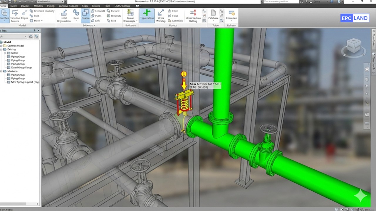
Figure 3: 3D Model showing the "New" branch (Green) intersecting the "Existing" Header (Grey) with interface support locations.
Project Constraints
- Operation: Hot Tap (Live Line Welding)
- Existing Line Age: 25 Years
- Space: Highly Congested Pipe Rack
Technical Risks
- Material: Carbon Equivalent / Weldability
- Stress: Additional Weight on Old Supports
- Code: ASME B31.3 Retrofit Rules
The Discipline Conflict
The Layout Engineer initially identified a tie-in location that offered the shortest route for the new line. However, this location was mid-span between two existing supports.
The Material Engineer flagged a concern: the existing header was an older specification of ASTM A53, while the new line was A106 Gr. B. Welding them required a specific procedure to avoid burn-through on the live line.
The Stress Engineer ran a preliminary check and immediately halted the design. Adding a heavy 12-inch valve assembly mid-span would cause the 25-year-old header to sag beyond acceptable limits, potentially rupturing the line during the hot tap operation.
The Integrated Solution
Through Interface Management meetings, the team devised a safe path forward:
- Relocation (Layout): The tie-in point was moved 1.5 meters closer to a main structural column, sacrificing the "straight run" for structural integrity.
- Reinforcement (Stress): The Stress Engineer modeled the combined system in Pipe Stress Analysis (CAESAR II). The analysis showed that the existing rack beam was overloaded. A new "dummy leg" support was designed to transfer the new valve weight directly to the column, bypassing the old pipe supports entirely.
- Verification (Material): Ultrasonic Thickness Testing (UTT) was ordered for the specific tie-in zone. The Material Engineer verified sufficient wall thickness remained to support the weld pool, creating a specialized "Hot Tap" Piping Material Specification (PMS) addendum.
Project Success Metrics
The collaborative approach prevented a potential containment loss.
- Safety: Zero Lost Time Injuries (LTI) during the high-risk Hot Tap execution.
- Reliability: Post-installation stress checks confirmed the existing header deflection was < 2mm, well within ASME B31.3 Code limits.
- Cost Avoidance: By relocating the tie-in based on Stress analysis, the project avoided a $250,000 shutdown required to strengthen the pipe rack beams.
EPCLand YouTube Channel
2,500+ Videos • Daily Updates
Frequently Asked Questions (FAQ)
Which of the Piping Engineering Disciplines comes first in a project?
Do I need to know CAESAR II to be a Layout Engineer?
How does the Piping Design Basis influence the project?
Can one engineer perform all three roles?
Final Thoughts: The Integrated Future
The era of siloed engineering is over. In 2026, the most valuable professionals are those who understand the friction points between the Piping Engineering Disciplines. A Layout Engineer who ignores stress physics will design a dangerous plant; a Stress Engineer who ignores constructability will design an expensive one.
Success lies in the synthesis. By mastering the Piping Material Specification, respecting the ASME B31.3 Code, and utilizing advanced tools like Pipe Stress Analysis (CAESAR II) in harmony, teams can deliver complex infrastructure that is safe, efficient, and built to last.

Related posts:
![Professional land surveyor using a total station for a topographic survey in an open field]()
Understanding Land Mapping and the True Topographic Survey Cost
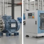
![Side-by-side comparison of an industrial centrifugal pump and a rotary screw compressor.]()
What is the Difference Between Pump and Compressor Systems?
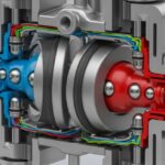
![Cutaway 3D render of an industrial air-operated double-diaphragm pump showing internal components.]()
Understanding Diaphragm Pumps: A Comprehensive Guide for Industrial Plants
![A metallic pipe sleeve embedded in a concrete wall with a carrier pipe passing through it.]()
What is a Pipe Sleeve and How Does It Protect Piping?
![Industrial stainless steel swing check valve installed in a pipeline with a flow direction arrow.]()
What are Check Valves? Types of Check Valves & Their Symbols
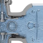
![Cross-section diagram of a control valve showing cavitation bubbles and flashing liquid.]()
How to Prevent Control Valve Cavitation and Flashing Damage