Piping Design Engineer: The 2026 Technical Handbook

A **Piping Design Engineer** is the architect of a process plant’s vascular system, responsible for the safe and efficient transport of fluids under extreme conditions. In 2026, the role has evolved far beyond simple drafting; it now demands a mastery of **ASME B31.3 Process Piping** codes, advanced **3D Plant Modeling (E3D/PDMS)**, and the ability to perform rigorous **Pipe Stress Analysis**. This guide dissects the technical competencies required to succeed in top-tier EPC firms.
What does a Piping Design Engineer do?
They are specialized mechanical engineers who design complex piping layouts for refineries, power plants, and petrochemical facilities. Their core deliverables include the **Piping Material Specification (PMS)**, Equipment Layouts, and **Piping Isometric Drawings**, ensuring all systems meet hydraulic requirements and safety codes like ASME B31.1 or B31.3.
Quick Navigation
Technical Skills Check
Question 1 of 51. Which ASME code governs Process Piping in refineries and chemical plants?
Complete Course on
Piping Engineering
Check Now
Key Features
- 125+ Hours Content
- 500+ Recorded Lectures
- 20+ Years Exp.
- Lifetime Access
Coverage
- Codes & Standards
- Layouts & Design
- Material Eng.
- Stress Analysis
1. The Regulatory Backbone: ASME Codes & Standards
For a professional Piping Design Engineer, the codebook is law. Unlike general mechanical design, piping systems in volatile environments (Refineries, Chemical Plants) are strictly regulated to prevent catastrophic containment loss. The primary governing document for 2026 remains ASME B31.3 Process Piping.
This code dictates everything from material selection to examination requirements. While ASME B31.1 covers Power Piping (steam generation), ASME B31.3 Process Piping is the broader standard applied to petrochemical complexes. A competent engineer must also be fluent in component standards, such as ASME B16.5 (Flanges) and ASME B16.9 (Fittings), ensuring that every bolt and gasket is rated for the line's design pressure and temperature.
The Piping Material Specification (PMS)
Before a single line is routed in the 3D model, the Piping Material Specification (PMS) (often called the "Pipe Class") must be defined. This document groups compatible components based on fluid service. For example, a "Class 150CS" spec might dictate ASTM A106 Gr. B pipe, A105 flanges, and Spiral Wound Gaskets. The Piping Design Engineer creates this spec to ensure uniformity and prevent the accidental mixing of incompatible materials, such as mating a Carbon Steel flange to a Stainless Steel pipe in a corrosive service.
2. The Design Workflow: From Plot Plan to Iso
Equipment Layout Design
The lifecycle begins with Equipment Layout Design (or Plot Plan development). Here, the engineer positions pumps, vessels, and columns to optimize flow paths and maintenance access. A poor layout results in excessive pipe runs, high pressure drops, and expensive support structures. The goal is to minimize the "pipe rack footprint" while adhering to safety spacing requirements (e.g., keeping ignition sources away from volatile storage).
3D Plant Modeling (E3D/PDMS)
Once the layout is frozen, the work moves into the digital twin environment. Modern execution relies heavily on 3D Plant Modeling (E3D/PDMS) suites (like AVEVA E3D or Hexagon Smart3D). In this environment, the Piping Design Engineer routes pipes in a collision-free manner, managing interferences with structural steel, cable trays, and HVAC ducts. This "clash detection" phase is critical for constructability, saving millions in field rework.
Piping Isometric Drawings
The final output of the design phase is the Piping Isometric Drawing. Unlike an orthographic plan view, the isometric is a non-scaled, single-line representation used by the fabrication shop to cut and weld the spool pieces.
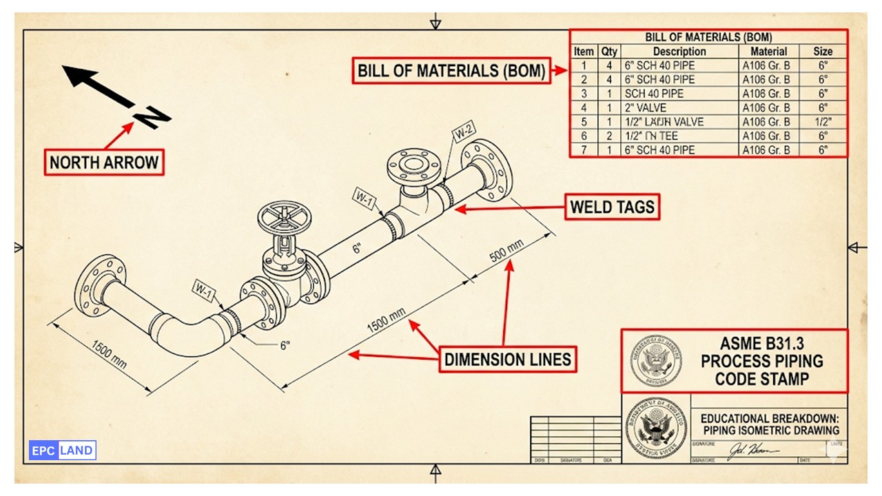
Figure 2: A typical fabrication isometric showing dimensions, weld tags, and the Bill of Materials (BOM).
3. Fundamental Engineering Calculations
While software handles complex simulations, a skilled Piping Design Engineer must manually verify wall thicknesses and span limits. The most fundamental calculation comes directly from ASME B31.3 Process Piping paragraph 304.1.2: determining the minimum required wall thickness to withstand internal pressure.
Code Calculation: Pressure Design Thickness
To ensure the pipe won't burst under operating pressure, use the B31.3 formula:
- t = Pressure design thickness (mm or in).
- P = Internal Design Pressure (psig or bar).
- D = Outside Diameter of pipe (mm or in).
- S = Allowable Stress of material at design temperature (from Code Table A-1).
- E = Quality Factor (usually 1.0 for seamless pipe).
- Y = Temperature Coefficient (0.4 for Ferritic steels below 482°C).
Engineering Tip: After calculating t, you must add the Corrosion Allowance (CA) and the Mill Tolerance (usually 12.5%) to select the final Commercial Schedule (e.g., Sch 40, Sch 80).
Common Pipe Schedules & Dimensions (ASME B36.10)
| NPS (Inch) | Outside Diameter (mm) | Sch 40 Thickness (mm) | Sch 80 Thickness (mm) | Max Span (Water Service) (m) |
|---|---|---|---|---|
| 2" | 60.3 | 3.91 | 5.54 | 3.4 |
| 4" | 114.3 | 6.02 | 8.56 | 4.9 |
| 6" | 168.3 | 7.11 | 10.97 | 6.1 |
| 8" | 219.1 | 8.18 | 12.70 | 7.0 |
| 10" | 273.0 | 9.27 | 15.09 | 7.9 |
Case Study: Critical Pipe Stress Analysis Topic: Thermal Expansion in High-Pressure Steam Lines
The ultimate test of a **Piping Design Engineer** is not just routing pipe that fits, but routing pipe that survives. In this case study, we examine a real-world scenario involving a 10-inch High-Pressure (HP) Steam line connecting a Utility Boiler to a Steam Turbine Generator (STG). The challenge was strictly related to **ASME B31.3 Process Piping** flexibility requirements: dealing with massive thermal growth.

Figure 3: CAESAR II Stress Contour Plot showing high stress concentration (Red) at the elbow of the expansion loop.
Design Parameters
- Service: HP Steam (Superheated)
- Line Size: 10-inch (Sch 80)
- Temperature: 380°C (716°F)
The Constraint
- Distance: 45 meters (straight run)
- Calculated Growth: ~220mm
- Equipment Limit: NEMA SM23 (Turbine)
The Thermal Challenge
When Carbon Steel piping heats up from ambient installation temperature (21°C) to operating temperature (380°C), it expands significantly. The Piping Design Engineer calculated the thermal growth using the coefficient of thermal expansion. For a 45-meter straight run, the pipe wanted to grow approximately 220mm in length.
If this line were routed directly from the Boiler nozzle to the Turbine nozzle (a "hard pipe"), this 220mm of growth would act like a battering ram. The resulting force (F = kx) would exceed 50,000 Newtons, likely shearing the turbine bolts or cracking the boiler casing. A direct route was impossible.
Implemented Solution: The Expansion Loop
To absorb this growth, the engineering team utilized **3D Plant Modeling (E3D/PDMS)** to redesign the route, incorporating a strategic "U-shaped" expansion loop.
- Loop Sizing: A 6-meter by 4-meter expansion loop was introduced in the middle of the rack. As the long pipe legs expand, they push into the loop, causing the "legs" of the U to flex. This converts the dangerous axial force into a manageable bending moment at the elbows.
- Support Optimization: "Resting" supports were used to carry the weight, but low-friction PTFE slide plates were installed to allow the pipe to glide freely as it expanded.
- Spring Hangers: Near the turbine connection, Variable Spring Hangers were installed to accommodate the vertical thermal growth of the turbine casing itself, ensuring zero load transfer to the sensitive equipment.
Stress Analysis Results (CAESAR II)
The revised design was simulated using **Pipe Stress Analysis** software.
- Code Compliance: The maximum stress range at the loop elbows was 65% of the Allowable Stress (SA) defined in ASME B31.3.
- Equipment Safety: The forces and moments acting on the turbine flange fell well within the NEMA SM23 allowable limits.
- Fatigue Life: The design verified that the system could withstand 7,000 full thermal cycles (startup/shutdown) over the plant's 25-year life.
EPCLand YouTube Channel
2,500+ Videos • Daily Updates
Frequently Asked Questions (FAQ)
How do I become a certified Piping Design Engineer in 2026?
What is the difference between Pipe Schedule and Pipe Class?
Why is Pipe Stress Analysis required for some lines but not others?
What software tools must a Piping Design Engineer know?
Final Thoughts: The Architect of the Plant
The role of the Piping Design Engineer sits at the intersection of creativity, physics, and rigorous code compliance. It is not merely about connecting Point A to Point B; it is about designing a system that is constructible, maintainable, and safe under extreme pressure.
As we move through 2026, the successful engineer will be the one who can bridge the gap between the Equipment Layout Design and the detailed physics of Pipe Stress Analysis. Whether you are generating a Piping Material Specification (PMS) or troubleshooting a thermal loop in the field, your work is the literal framework that holds the energy industry together.

Related posts:
![A mechanical sucker rod pumpjack operating in an oil field at sunset]()
What is Sucker Rod Pump System in Oil Production?
![Piping material engineer reviewing technical specifications on a tablet in an industrial plant.]()
How a Piping Material Engineer Drives Industrial Project Success
![Industrial refinery plant showing various types of static equipment]()
What is Static Equipment? Types and List of Static Equipments
![Side-by-side comparison of industrial process piping and power plant steam piping systems.]()
Differences Between ASME B31.3 and B31.1: B31.3 vs B31.1
![Large industrial steel storage tank under construction with cranes and scaffolding]()
Storage Tank Construction Method Statement: Step-by-Step Engineering Guide
![Cutaway diagram of a globe control valve highlighting the internal valve trim components]()
What is a Valve Trim? Types, Components, and Selection


