Petrochemical Plant Process: A Complete Engineering Guide

The Petrochemical Plant Process is the industrial engine that transforms raw hydrocarbon feedstocks into the molecular building blocks of modern life. In 2026, the engineering spotlight is fixed on the **Steam Cracking Process**—the heart of the facility—where intense heat breaks stable bonds to create reactive olefins like Ethylene and Propylene. This guide decomposes the complex flow schemes, from **Naphtha Cracking** furnaces to the cryogenic separation cold box, providing a blueprint for process optimization.
What is the Petrochemical Plant Process?
It is a sequence of chemical engineering operations designed to convert feedstocks (like Naphtha, Ethane, or Propane) into primary petrochemicals (Ethylene, Propylene, Butadiene, Aromatics). The core mechanism is thermal pyrolysis (cracking) followed by rapid quenching, compression, and cryogenic distillation to separate products by boiling point.
Quick Navigation
Test Your Process Knowledge
Question 1 of 51. What is the primary function of the Steam Cracker Furnace?
Complete Course on
Piping Engineering
Check Now
Key Features
- 125+ Hours Content
- 500+ Recorded Lectures
- 20+ Years Exp.
- Lifetime Access
Coverage
- Codes & Standards
- Layouts & Design
- Material Eng.
- Stress Analysis
1. Fundamentals of the Steam Cracking Process
The Petrochemical Plant Process is dominated by one primary unit operation: Pyrolysis. Unlike oil refining, which separates existing molecules, petrochemical processing involves chemically breaking them apart. This is achieved through the Steam Cracking Process, where hydrocarbon feedstocks are diluted with steam and briefly exposed to extreme temperatures (800°C to 900°C) inside a radiant coil.
The physics here are brutal but precise. The heat energy vibrates the carbon-carbon bonds until they snap (fission), creating free radicals. These radicals immediately rearrange into unsaturated molecules—primarily Ethylene (C2H4) and Propylene (C3H6). In 2026, the industry is also integrating "E-Furnaces" (electric heating) to decarbonize this energy-intensive step, marking a significant evolution in the Petrochemical Plant Process.
The Ethylene Production Flow Scheme
To visualize the transformation, engineers utilize a Process Flow Diagram (PFD). This diagram traces the molecule's journey from the furnace inlet through the complex cooling and separation trains.
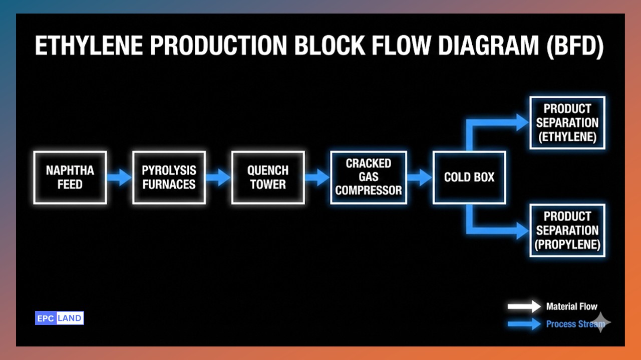
Figure 2: Block Flow Diagram of a Typical Naphtha Cracker Complex.
2. Key Unit Operations Breakdown
The "Hot Section": Cracking & Quench
The process begins with Naphtha Cracking (or Gas Cracking). The feedstock enters the convection section of the furnace to be preheated, mixed with dilution steam, and then blasted through the radiant coils. The residence time here is measured in milliseconds (0.1 to 0.5 seconds).
Crucially, the reaction must be stopped immediately to prevent the olefins from degrading into secondary byproducts or coke. This is done in the Quench Tower (or Transfer Line Exchanger - TLE), where the temperature is dropped from 850°C to 400°C in fractions of a second, generating high-pressure steam in the process.
Cracked Gas Compression (CGC)
The "Cracked Gas" is now a massive volume of low-pressure gas. To separate its components, it must be compressed. The Cracked Gas Compressor (CGC) is typically a 4 or 5-stage centrifugal machine. Between stages, acid gases (CO2 and H2S) are removed in a caustic scrub tower. This is vital because CO2 freezes at the low temperatures found in the downstream Cold Box, potentially blocking the lines.
The "Cold Section": Cryogenic Separation
This is where the Ethylene Production Flow moves into sub-zero engineering. Using a series of distillation columns (Demethanizer, Deethanizer, C2 Splitter), the mixture is separated by boiling point.
- Demethanizer: Removes Methane (C1) and Hydrogen (H2) at -140°C.
- Deethanizer: Separates C2s (Ethane/Ethylene) from heavier C3+ components.
- C2 Splitter: The most difficult separation. It splits Ethane (recycled to furnace) from Ethylene (99.9% purity product).
Downstream: Aromatics & Polymers
The heavier fractions from Naphtha cracking (C6+) are sent to the Aromatics Extraction Unit. Here, valuable solvents like Benzene, Toluene, and Xylene (BTX) are recovered. Meanwhile, the pure Ethylene and Propylene are piped to the Polymerization Process units, where catalysts link the monomers into long chains of Polyethylene (PE) and Polypropylene (PP)—the final solid products sold to manufacturers.
Feedstock vs. Product Yield Comparison
Engineers select feedstocks based on the desired "severity" and market demand for byproducts (Pygas/Propylene).
| Feedstock Type | Ethylene Yield (%) | Propylene Yield (%) | Pygas/Aromatics Yield (%) | Complexity |
|---|---|---|---|---|
| Ethane (Gas) | 78 - 80% | 1 - 3% | < 1% | Low |
| Propane (Gas) | 40 - 45% | 15 - 20% | 2 - 4% | Medium |
| Naphtha (Liquid) | 30 - 35% | 13 - 17% | 15 - 20% | High |
| Gas Oil (Heavy Liquid) | 20 - 25% | 10 - 15% | 20 - 30% | Very High |
Engineering Insight: Residence Time Calculation
In the radiant coil, the Residence Time (t) determines the conversion severity. If the gas stays too long, it over-cracks into coke and methane. If it's too fast, conversion is low.
- t = Residence time (seconds).
- V_coil = Internal volume of the radiant coil (m³).
- Q_gas = Volumetric flow rate of the gas at reaction conditions (m³/s).
Note: Since the gas expands rapidly due to cracking (increasing molar volume) and temperature rise, Q_gas is not constant. Engineers use an average integrated flow rate across the coil length to estimate the true residence time, typically aiming for 0.2 - 0.4 seconds.
Case Study: Steam Cracker Radiant Coil Fouling Topic: Maximizing Run Length & TMT Management
In the **Petrochemical Plant Process**, the profitability of the ethylene unit is directly tied to the "Run Length" of the furnaces. During the **Steam Cracking Process**, carbon (coke) inevitably deposits on the inner walls of the radiant coils. This coke layer acts as an insulator, forcing operators to increase the firing rate to maintain the required Coil Outlet Temperature (COT). Eventually, the Tube Metal Temperature (TMT) hits its metallurgical limit, forcing a shutdown for decoking.
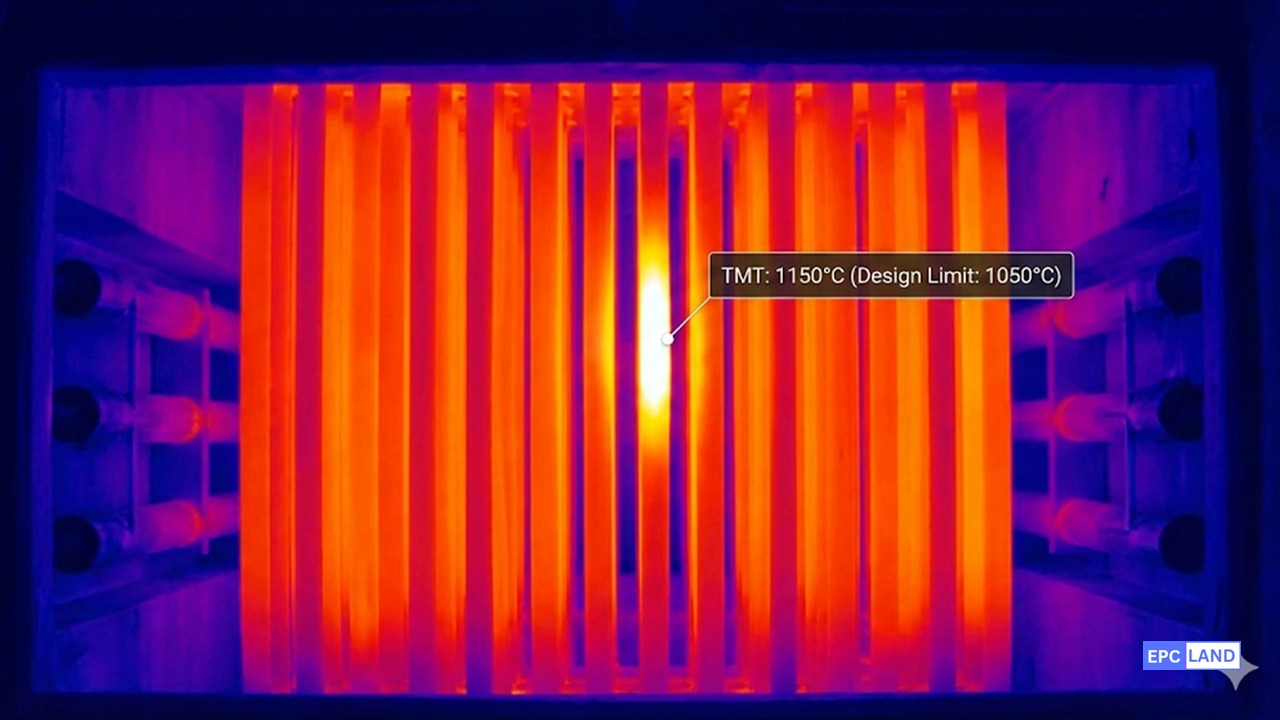
Figure 3: Thermal imaging revealing a TMT "Hot Spot" (1080°C) due to localized coke buildup.
Equipment Specs
- Unit: Naphtha Steam Cracker (1.2 MTA Capacity)
- Furnace Type: SRT (Short Residence Time) VI
- Metallurgy: High-Alloy Centrifugally Cast (Cr-Ni)
Failure Conditions
- Max Design TMT: 1100°C
- Observed TMT: 1115°C (Safety Trip)
- Run Length: Reduced to 35 days (Target: 60)
Root Cause Analysis
The engineering team analyzed the operational data and identified two concurrent issues shortening the run length:
- Over-Cracking (High Severity): The Propylene-to-Ethylene (P/E) ratio indicated the furnace was operating at a severity higher than design, leading to excessive "Pyrolytic Coking" (coke formed in the gas phase depositing on the wall).
- Flame Impingement: Misaligned floor burners were directing flames directly onto the lower radiant coils, creating localized hot spots. This caused "Catalytic Coking" to accelerate exponentially at those specific points, as seen in Figure 3.
The coke layer increased the thermal resistance. To maintain the process temperature of 835°C (COT), the external tube temperature had to be pushed beyond the material's creep rupture limit.
Implemented Solution
To optimize the **Petrochemical Plant Process** reliability, a maintenance and control strategy was deployed:
- Burner Tuning: During the shutdown, the burner tips were replaced and aligned to ensure a flat, vertical flame profile, eliminating direct impingement on the coils.
- Anti-Coking Agents: A sulfur-based dosing system (DMDS - Dimethyl Disulfide) was recalibrated. Sulfur passivates the active nickel sites on the coil surface, significantly retarding the initial rate of catalytic coking.
- COT Control Logic: The control loop was adjusted to "Start of Run" (SOR) gentle ramping, gradually increasing severity only as the coke layer stabilized, rather than forcing high severity immediately after decoking.
Operational ROI & Results
The adjustments successfully managed the TMT rise rate.
- Run Length Extension: Increased from 35 days to 58 days on average.
- Production Gain: 23 fewer decoking days per year resulted in an additional 4,500 tons of Ethylene production.
- Asset Life: Reduced thermal cycling stress on the radiant coils, extending the tube replacement interval by 2 years.
EPCLand YouTube Channel
2,500+ Videos • Daily Updates
Frequently Asked Questions (FAQ)
What is the difference between an Oil Refinery and a Petrochemical Plant?
Why is the Aromatics Extraction Unit only found in certain complexes?
How does "Severity" impact the Ethylene Production Flow?
What is the role of the Process Flow Diagram (PFD) in safety?
Final Thoughts on Petrochemical Engineering
The Petrochemical Plant Process represents the pinnacle of thermal and cryogenic engineering. From the extreme heat of the radiant coils to the deep freeze of the demethanizer, every degree of temperature change is calculated to maximize yield and margin.
As we advance through 2026, the industry faces dual challenges: maintaining the reliability of the **Ethylene Production Flow** while integrating decarbonization technologies like electric furnaces. For the EPC engineer, success lies in mastering the balance between reaction kinetics, hydraulic constraints, and the material limits of the equipment.

Related posts:
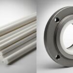
![Comparison of raw PTFE material and an industrial PTFE-lined steel pipe flange]()
Teflon vs PTFE: Major Differences in Industrial Piping Applications
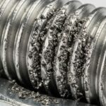
![Severe metal galling damage on a stainless steel threaded bolt and nut.]()
What is Metal Galling and How to Prevent It
![Certified welder performing structural welding repair on a heavy steel beam with sparks flying.]()
Mastering Industrial Welding Repair Procedures for Structural Integrity
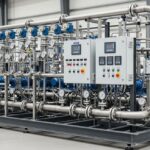
![A fully assembled industrial pump skid system with stainless steel piping and control panels in a factory.]()
What is an Industrial Pump Skid and Its Key Advantages?
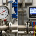
![Side-by-side comparison of an industrial flow meter and a digital flow transmitter installed on a pipeline.]()
Flow Transmitter vs Flow Meter: Key Differences Explained
![Wireless vibration sensor mounted on an industrial electric motor for condition monitoring.]()
What is Vibration Monitoring and Why is it Important?