Post Weld Heat Treatment (PWHT): The Complete Engineering Guide
Post Weld Heat Treatment (PWHT) is a critical thermal process applied to welded materials to reduce residual stresses and restore the mechanical properties of the steel. In high-pressure piping and vessel fabrication, performing accurate PWHT is often the deciding factor between a compliant, long-lasting joint and a catastrophic failure due to stress corrosion or brittle fracture.
What is the main purpose of PWHT?
The primary goal is residual stress relief welding. By heating the material to a specific temperature below its critical transformation point and holding it there, the internal stresses caused by the rapid heating and cooling of the welding arc are released, preventing future cracking.
📖 Quick Navigation
⚡ Engineering Knowledge Check
Question 1 of 5📝 Explanation:
Complete Course on
Piping Engineering
Check Now
Key Features
- 125+ Hours Content
- 500+ Recorded Lectures
- 20+ Years Exp.
- Lifetime Access
Coverage
- Codes & Standards
- Layouts & Design
- Material Eng.
- Stress Analysis
1. Theory & ASME Code Requirements
When metal is welded, the localized heat input creates steep thermal gradients. As the weld pool solidifies and cools, it contracts, but the surrounding cooler base metal restricts this contraction. This conflict generates high-magnitude internal forces known as residual stresses. If left untreated, these stresses can equal or exceed the yield strength of the material, leading to catastrophic failures like Brittle Fracture or Stress Corrosion Cracking (SCC).
Why “Residual Stress Relief Welding” Matters
The process of Post Weld Heat Treatment acts as a controlled relaxation method. By elevating the material’s temperature to a point where the yield strength decreases (typically 595°C to 760°C for steels), the material can micro-plastically deform (creep) to relieve these locked-in stresses. This residual stress relief welding technique effectively “resets” the material’s internal state without altering its shape.
ASME B31.3 PWHT Requirements
In the oil and gas industry, ASME B31.3 PWHT requirements dictate exactly when this treatment is mandatory. The code groups base metals into “P-Numbers” to simplify the rules. For example, while standard Carbon Steel (P-No. 1) only requires PWHT if the wall thickness exceeds 19mm (3/4 inch), alloy steels like P-No. 5 (Chrome-Moly) require it regardless of thickness to prevent hydrogen cracking.
2. The PWHT Process Cycle
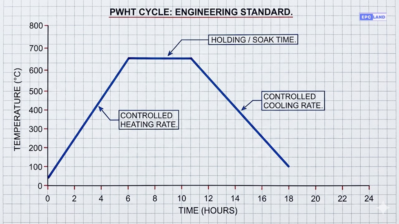
A successful heat treatment cycle is defined by three critical parameters: the heating rate, the soak (holding) period, and the cooling rate. Ignoring any one of these can ruin the metallurgical properties of the piping.
Controlling Heating and Cooling Rates
The heat treatment heating and cooling rates must be strictly controlled to avoid thermal shock. If you heat a thick pipe too quickly, the outside expands faster than the inside, causing new stresses. ASME B31.3 typically limits the heating rate to roughly 222°C/hr (400°F/hr) divided by the thickness in inches.
🧮 Calculation: Minimum Soak Time
The PWHT holding time and temperature are inversely related, but codes set a minimum floor. For thicknesses up to 2 inches (50mm), the rule of thumb is:
Example: For a 1.5-inch thick weld, the Minimum Holding Time is 1.5 Hours (90 minutes).
Note: Minimum is usually 15 minutes regardless of thinness.
Local PWHT vs Furnace Heating
Engineers often choose between local PWHT vs furnace heating based on the component size.
- Furnace PWHT: The entire spool or vessel is placed in a large oven. This is ideal for complex geometries as it ensures uniform temperature distribution.
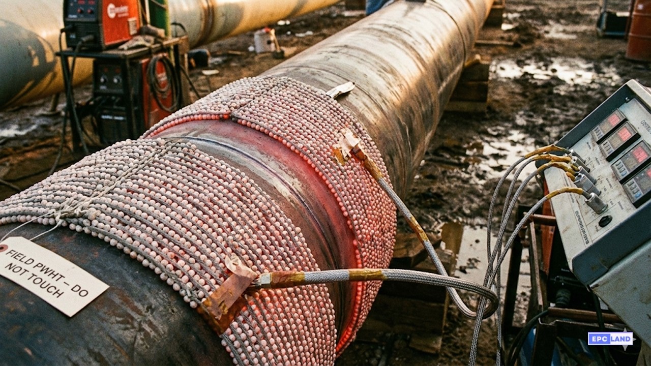
- Local PWHT: Ceramic heating pads are wrapped around the weld band (plus a gradient zone). This is standard for field erection welds where the pipe is already installed.
📊 ASME B31.3 Typical PWHT Parameters
Always consult the specific WPS and Code edition. Values below are general guidelines for 2026.
| P-Number | Material Type | Holding Temp Range | Min Holding Time (Up to 2″) |
|---|---|---|---|
| P-No. 1 | Carbon Steel | 595°C – 650°C (1100°F – 1200°F) | 1 Hr/inch (Min 15 min) |
| P-No. 3 | Alloy Steel (0.5% Cr – 2% Cr) | 595°C – 715°C (1100°F – 1320°F) | 1 Hr/inch (Min 15 min) |
| P-No. 4 | Alloy Steel (1.25% Cr) | 705°C – 760°C (1300°F – 1400°F) | 1 Hr/inch (Min 30 min) |
| P-No. 5A/5B | Chrome-Moly (2.25% Cr – 9% Cr) | 705°C – 760°C (1300°F – 1400°F) | 1 Hr/inch (Min 1 Hr) |
| P-No. 8 | Stainless Steel (Austenitic) | None Required | N/A |
⚙️ How is PWHT Performed?
Achieving the optimum result requires a systematic, three-stage approach. The process is not just about “heating it up,” but rigidly controlling the entire thermal profile.
Heating Phase
The component is gradually heated to a temperature below its lower critical transformation temperature.
Control Requirement: The heating rate must be slow and controlled (e.g., < 220°C/hr per inch) to prevent thermal shock, which could introduce new stresses or distort the component.
Holding Phase
Also known as the “Soak Period.” The temperature is maintained at the specific target (e.g., 600°C – 650°C for Carbon Steel) for a determined duration.
Optimum Condition: This allows for uniform heat distribution through the thickness and enables the microstructure to relax (creep), effectively removing the residual stresses.
Cooling Phase
The workpiece is cooled slowly to ambient temperature under insulation.
Critical Warning: Rapid cooling (quenching) is forbidden. Controlled cooling is essential to avoid re-hardening the steel or causing brittle cracking.
🎯 Achieving Optimum Welding Conditions
To ensure the PWHT is successful and the “Optimum Condition” of the metal is restored, three key variables must be evaluated before starting:
1. Material Type
Chemical composition dictates the temperature. Carbon steel requires ~600°C, while P91 requires ~760°C. Wrong temp = Ruined metallurgy.
2. Wall Thickness
Thickness governs the Soak Time (1 hr/inch) and the maximum heating rate. Thicker metals require slower heating to avoid gradients.
3. Prior Treatments
Has the steel been quenched and tempered (Q&T)? If so, the PWHT temp must be lower than the original tempering temp to maintain strength.
Case Study: Stress Corrosion Cracking in Amine Piping
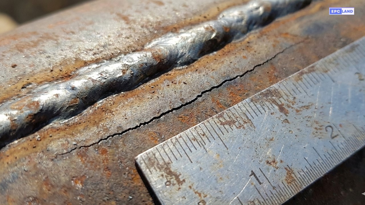
Fig 2. Intergranular cracking observed in the Heat Affected Zone (HAZ) of a non-stress-relieved weld.
Facility Location
Gulf Coast Refinery, USA
Equipment
Lean Amine Return Line (6″ NPS)
Material
ASTM A106 Gr. B (Carbon Steel)
❌ The Failure
Approximately 8 months after commissioning, a leak was detected at a field butt weld on the Amine Return line. Ultrasonic testing revealed extensive cracking running parallel to the weld fusion line. The piping thickness was only 10mm (0.4 inches). Under standard ASME B31.3 PWHT requirements for P-No 1 Carbon Steel, PWHT is typically not mandatory until 19mm thickness. Consequently, the construction team had skipped the stress relief process to save time.
🔍 Root Cause Analysis
The failure mechanism was identified as Alkaline Stress Corrosion Cracking (ASCC). While the wall thickness did not trigger a mandatory PWHT per the pressure design code, the service environment (Amine) is highly corrosive to carbon steel in the presence of residual stresses. The welding process left high tensile stresses in the HAZ, which, combined with the caustic amine solution, initiated the cracks.
✅ The Solution & Verification
The failed spool was cut out and replaced. A mandatory PWHT cycle was specified for the repair: heating to 620°C ±10°C for 1 hour, wrapped with local ceramic heating pads.
To ensure the stress relief was effective, the QA team performed Brinell hardness testing after PWHT directly on the weld cap and HAZ. The target was to ensure the hardness remained below 200 HB (Hardness Brinell), confirming that the microstructure had sufficiently softened to resist future cracking.
EPCLand YouTube Channel
2,500+ Videos • Daily Updates
Technical Distinction: Preheating vs. PWHT
A common confusion in the field is the difference between Preheating and PWHT. While both involve thermal application, their objectives are fundamentally different. Preheating is a preparatory step to prevent hydrogen-induced cracking, while PWHT is a post-process step for residual stress relief.
| Feature | Preheating | Post Weld Heat Treatment (PWHT) |
|---|---|---|
| Primary Purpose | Prevent hydrogen cracking & slow cooling rate | Relieve residual stresses & temper hardness |
| Timing | Before and during welding | After welding is completed |
| Temp Range | 50°C to 300°C (120°F – 570°F) | 595°C to 760°C (1100°F – 1400°F) |
| Typical Method | Gas burners, induction, or electric blankets | Precise controlled furnace or localized electric pads |
⚠️ Common Challenges in PWHT
💸 Cost Implications
High energy consumption and equipment rental costs for large vessels can significantly impact project budgets.
⏱️ Time Constraints
Thick-walled reactors may require 24-48 hour cycles. This downtime must be factored into the critical path schedule.
🧠 Expertise Required
Improper thermocouple placement or insulation gaps can lead to uneven heating, rejecting the entire heat cycle.
🚀 Key Advantages of PWHT
- ✓ Stress Relief: Significantly reduces internal tensile stresses that lead to Stress Corrosion Cracking (SCC).
- ✓ Brittle Fracture Prevention: Restores ductility and toughness to the Heat Affected Zone (HAZ).
- ✓ Dimensional Stability: Prevents distortion or “ovality” during subsequent machining operations.
- ✓ Code Compliance: Ensures full adherence to ASME Section VIII and B31.3 legality requirements.
🛠️ Site Execution Best Practices
- ➜ Thermocouple Contact: Ensure TCs are Capacitor-Discharge (CD) welded directly to the pipe for accurate readings.
- ➜ Insulation Width: Extend insulation at least 12 inches beyond the heating pads to prevent thermal gradients.
- ➜ Support the Load: Steel gets soft at 700°C. Support piping spans to prevent sagging during the heat cycle.
- ➜ Clean Surface: Remove oil, grease, or sulfur compounds before heating to avoid surface contamination.
3. Common PWHT & Preheating Techniques
🔥 Methods of Heat Application
🏭 Furnace Heating
Best for: Large vessels, spools, or multiple parts.
The entire component is placed in a large oven. This guarantees the most uniform heating and controlled cooling rates, eliminating thermal gradients.
⚡ Local Resistance
Best for: Site welds, pipelines, and tie-ins.
Utilizes flexible ceramic heating pads (beads) wrapped around the weld. It allows for heat treatment without moving the pipe but requires careful insulation.
🧲 Induction Heating
Best for: Complex geometries & speed.
Uses electromagnetic fields to generate heat within the metal itself. It is highly efficient and precise, making it ideal for uniform heating of thick-walled components.
Preheating Specific Tools
Unlike PWHT which requires strict control, preheating (50°C – 300°C) allows for more varied application methods:
- Gas Burners: Direct flame (rosebud) for quick localized heat.
- Electric Blankets: For maintaining steady interpass temp.
- Induction: Quickest for thick base metals.
- Ovens: For batch preheating small parts.
🌍 Key Industries
Sectors that heavily rely on PWHT for structural integrity:
- 🛢️ Petrochemical & Refineries: Protection against Amine/Caustic SCC.
- ⚡ Power Generation: Boilers, Turbines, and High-Pressure Steam lines.
- ⚓ Offshore & Marine: Subsea pipelines subject to high fatigue loads.
- 🏭 Pressure Vessels: Heavy wall reactors and storage tank fabrication.
🧪 Materials Requiring PWHT
Common material grades that necessitate thermal treatment:
Carbon Steel (P-No 1)
Mandatory >19mm thickness or in sour/lethal service.
Alloy Steel (Chrome-Moly)
P11, P22, P91. Almost always requires PWHT to prevent cracking.
Stainless Steel
Generally exempt (Austenitic), but required for Martensitic grades.
? Frequently Asked Questions
Is PWHT required for all Carbon Steel welds? ▼
No. Under standard ASME B31.3 PWHT requirements, Carbon Steel (P-No. 1) is typically exempt from post weld heat treatment if the material thickness is less than 19mm (3/4 inch). However, exceptions exist for specific service environments (like Caustic, Amine, or Sour Service) where PWHT is mandatory regardless of thickness to prevent stress corrosion cracking.
Can I use a rosebud torch for PWHT? ▼
Absolutely not for code-compliant piping. A manual torch cannot maintain the strict heat treatment heating and cooling rates required by code. Uneven heating from a torch introduces new thermal stresses rather than relieving them. Controlled electric resistance heating pads or induction heating must be used to ensure uniform temperature control.
What is the difference between Pre-heating and PWHT? ▼
Pre-heating is applied before and during welding to drive off moisture and slow down the cooling rate of the weld pool, preventing hydrogen cracking. Post Weld Heat Treatment is applied after welding is complete to relieve residual stresses and temper the metal. They serve different metallurgical purposes but are often used together on alloy steels.
How is temperature verified during field PWHT? ▼
Thermocouples (typically Type K) are capacitor-discharged welded directly to the pipe surface before the heating pads are applied. These are connected to a chart recorder or digital data logger to produce a “Time-Temperature” chart. This chart is the legal record proving the PWHT holding time and temperature parameters were met.
Final Thoughts for the Engineer
Post Weld Heat Treatment is not just a “box-checking” exercise; it is a fundamental safeguard for the integrity of high-pressure assets. Whether you are dealing with P91 chrome-moly piping or standard carbon steel in sour service, understanding the physics of residual stress relief welding is key.
Always reference the latest 2026 editions of ASME B31.3 or ASME Section VIII Div 1 before finalizing your Welding Procedure Specification (WPS). A skipped PWHT cycle today could mean a catastrophic leak tomorrow.
© 2026 Epcland. All Engineering Rights Reserved.

Related posts:
![Professional wind turbine technicians performing high-altitude maintenance on a nacelle at a large-scale wind farm.]()
Wind Farm O&M: Strategies for Maximum Operational Reliability and Efficiency
![Utility-scale wind power plant with multiple turbines in a field at sunset, representing Wind Power Plant Economics and infrastructure.]()
Wind Power Plant Economics: Mastering LCOE and Project Financials
![Aerial view of a wind farm integrated with a large-scale containerized Battery Energy Storage Systems facility for grid stability.]()
Battery Energy Storage Systems for Wind Projects: Design and Integration
![Technical view of a wind farm substation connecting wind turbines to the high-voltage electrical transmission grid.]()
Grid Integration of Wind Power Plants: Technical Design and Standards
![Cross-section diagram of a reinforced concrete gravity foundation for an onshore wind turbine showing steel rebar cage and anchor bolts.]()
Wind Turbine Foundations Explained: Design, Geotechnical, and Construction Methods
![Aerial view of a utility-scale wind farm showing turbine arrays, underground collector cable routes, and a central step-up substation.]()
Wind Farm Electrical System Design: A Comprehensive Engineering Guide