Valve Trim: The Engineering Guide to Types, Materials & API 600
Valve Trim represents the internal “wetted” parts of a valve that come into direct contact with the process fluid, governing flow control and sealing capability. While the valve body serves as the pressure vessel, the trim—consisting principally of the stem, seat, disc (or plug), and internal hardware—dictates the valve’s performance, longevity, and resistance to severe service conditions like cavitation and flashing.
What is Valve Trim?
In engineering terms, Valve Trim includes all internal components responsible for flow modulation and shut-off. According to API and ASME standards, the core trim components are the Stem, Seating Surface, and Closure Element (Disc/Plug). Proper selection of trim materials (based on API 600 charts) is critical for preventing erosion, corrosion, and galling.
Quick Navigation
🧠 Test Your Valve Knowledge
Loading…
Complete Course on
Piping Engineering
Check Now
Key Features
- 125+ Hours Content
- 500+ Recorded Lectures
- 20+ Years Exp.
- Lifetime Access
Coverage
- Codes & Standards
- Layouts & Design
- Material Eng.
- Stress Analysis
Valve Trim Theory: The Physics of Flow Control
The longevity of any piping system depends heavily on the Valve Trim. While the valve body acts as the static pressure boundary, the trim is the dynamic interface. It is responsible for absorbing the high kinetic energy generated when a fluid undergoes a pressure drop. In high-pressure applications, the trim must withstand extreme velocities, often exceeding Mach 1 in gas services or causing cavitation in liquids.
The primary failure modes for trim components are erosion, corrosion, and seizing (galling). When selecting a valve, engineers must calculate the Flow Coefficient (Cv) to ensure the trim size is adequate for the required flow rate without causing excessive velocity.
💡 Engineering Formula: Flow Coefficient (Cv)
Cv = Q × √( SG / ΔP )
- Cv = Valve Flow Coefficient
- Q = Flow Rate (US Gallons per minute)
- SG = Specific Gravity of fluid (Water = 1)
- ΔP = Pressure Drop across the valve (psi)
API 600 Trim Chart & Material Selection
For steel gate, globe, and check valves, the API 600 Trim Chart is the global standard for specifying materials. This system assigns a unique number to specific material combinations for the stem, seat surface, and wedge/disc surface. Proper Valve Trim Materials Selection is vital; a mismatch (e.g., using soft stainless steel in high-temp steam) will lead to rapid galling.
The most common configuration is Trim #8 (Universal Trim), which combines a 13% Chromium (410 SS) stem with Stellite Hardfacing on the seat rings. Stellite (Cobalt-Chromium-Tungsten) provides exceptional resistance to galling and high-temperature oxidation.
| Trim No. | Common Name | Stem Material | Seat Surface / Disc Surface | Typical Service |
|---|---|---|---|---|
| Trim 1 | F6 (13Cr) | 13% Cr (410 SS) | 13% Cr (410 SS) | General Oil, Gas, Water (Non-Corrosive) |
| Trim 5 | Hardfaced | 13% Cr (410 SS) | Stellite (Co-Cr-W) | High Pressure Steam, abrasive fluids |
| Trim 8 | Universal (F6 + HF) | 13% Cr (410 SS) | Stellite / 13% Cr | Standard for Refinery & Power (Temp < 850°F) |
| Trim 10 | 316 SS | 316 SS | 316 SS | Corrosive Service, Acid, Sour Gas |
| Trim 12 | 316 + HF | 316 SS | Stellite / 316 SS | High Temp Corrosive Service |
Control Valve Trim Types & Severe Service
While isolation valves use standard wedge or disc trims, Control Valve Trim Types are far more complex because they must throttle flow continuously. The geometry of the plug and cage determines the flow characteristic (Linear, Equal Percentage, or Quick Opening).
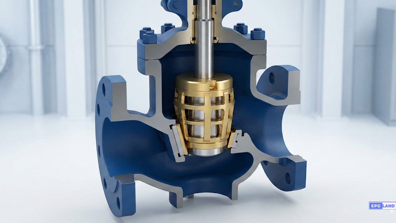
1. Cage Guided Trim
The most versatile design. A cylindrical cage with holes (windows) surrounds the plug. As the plug lifts, more window area is exposed. This design allows for easy maintenance and excellent stability against vibration.
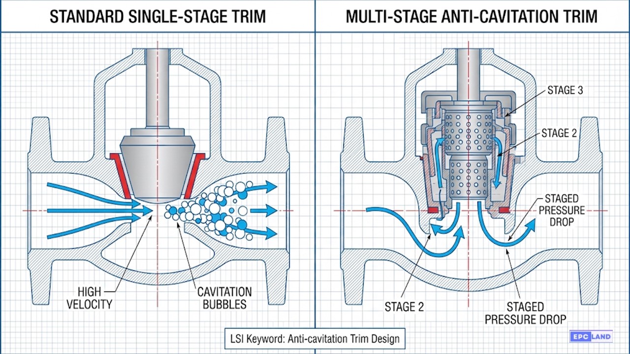
2. Anti-Cavitation Trim Design
In liquid applications with high pressure drops, fluid velocity increases, causing static pressure to fall below the vapor pressure. Bubbles form and then violently collapse when pressure recovers—this is cavitation. A standard single-stage trim will be destroyed by this.
To solve this, engineers use Anti-cavitation Trim Design (often called “Multi-Stage Trim”). By forcing the fluid through a tortuous path of small channels, the pressure drop is staged (broken into smaller steps), preventing the pressure from ever dipping below the vapor limit.
3. Severe Service Trim
Severe Service Trim is required when noise exceeds 85 dBA, cavitation is predicted, or the fluid contains abrasive particles. These trims often utilize Tungsten Carbide overlays or stacked-disc technologies (like labyrinth disks) to control velocity.

Core Trim Components & Definitions
Beyond the general definition, understanding the specific role of each Valve Trim component is essential for maintenance and assembly. The trim configuration dictates the valve’s ability to seal against pressure and regulate flow volume.
1. The Stem
The transmission rod that transfers torque or thrust from the actuator (or handwheel) directly to the internal plug or disc. In high-pressure valves, the stem must possess high tensile strength to overcome the thrust of the process fluid.
2. The Plug / Disc
The primary closure element. In Control Valves, it is called a “Plug” and determines flow characteristics. In Isolation valves, it is a “Disc” or “Wedge.” It can be cast, forged, or machined and requires a micro-polished surface to minimize friction.
3. The Seat Ring
Provides the stationary mating surface for the disc/plug. Seats may be threaded (replaceable) or welded (permanent) into the valve body. Soft seats (PTFE) offer zero leakage but low temp limits; Metal seats (Stellite) offer durability.
4. The Back Seat
A critical safety feature in gate and globe valves. It provides a secondary seal against the stem when the valve is fully open, preventing process fluid from leaking into the packing chamber and allowing for packing replacement under pressure (if permitted by safety protocols).
Valve Plug Characteristics & Flow Profiles
In control applications, the geometry of the Valve Trim Plug determines how the flow rate changes relative to the stem travel. This relationship is plotted as a “Flow Characteristic Curve.”
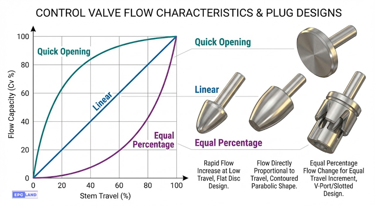
Quick Open Profile
Designed to release maximum flow with minimal stem movement. Typically, 90% of the flow capacity is achieved with just 30-40% of the lift. This profile is rarely used for throttling but is ideal for On-Off safety applications or relief valves where rapid relief is critical.
Linear Profile
Provides a direct 1:1 relationship between stem travel and flow rate. If the valve opens 50%, the flow is 50% of maximum. This Valve Trim type is preferred for liquid level control and systems where the valve pressure drop (ΔP) remains constant regardless of flow.
Equal Percentage Profile
The industry standard for pressure and temperature control loops. For every increment of stem travel, the flow changes by a consistent percentage of the current flow rate. This allows for precise throttling at low flow rates while maintaining capacity at high flow rates.
Advanced Material Selection for Corrosive Service
While API 600 charts cover standard hydrocarbons, special chemical processes require exotic Valve Trim Materials Selection.
| Trim Material | Key Characteristic | Target Application |
|---|---|---|
| Stainless Steel (316/304) | Balance of cost & corrosion resistance. | General Chemical, Food & Bev, Cryogenic. |
| Monel (Ni-Cu Alloy) | Excellent resistance to reducing acids & seawater. | HF Acid units, Marine/Offshore, Chlorine. |
| Alloy 20 | Specific resistance to Sulfuric Acid (H2SO4). | Fertilizer plants, Pickling lines. |
| Cu-Ni (Copper Nickel) | Anti-biofouling, resists salt corrosion. | Desalination, Firewater mains. |
| Hardened Trim (Tungsten) | Extreme hardness (>70 HRC) for abrasion. | Mining Slurry, Catalyst fines, Sand production. |
EPCLand YouTube Channel
2,500+ Videos • Daily Updates
Case Study: Valve Trim Erosion in High-Pressure Steam
Site Context
- Industry: Thermal Power Generation
- Application: HP Turbine Bypass (Steam Let-down)
- Fluid: Superheated Steam
Operating Conditions
- Inlet Pressure (P1): 2,400 psig
- Outlet Pressure (P2): 600 psig
- Temperature: 1050°F (565°C)
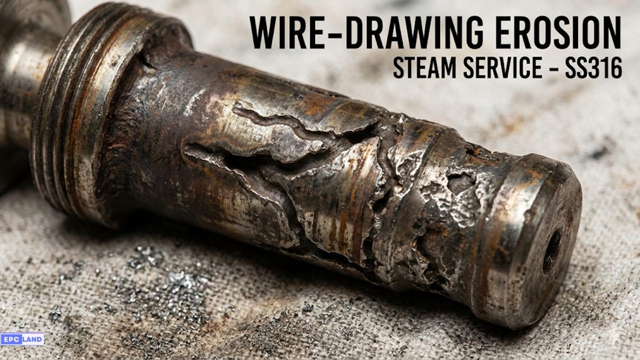
The Problem: Rapid Seat Failure
A 600MW power plant experienced repeated failures in their steam let-down station. The original globe valve utilized a standard single-stage parabolic plug **Valve Trim**. Within just 3 months of operation, the valve failed to shut off tightly (passing steam), creating a loud high-frequency noise and temperature spikes downstream.
Upon disassembly, the maintenance team discovered deep “wormhole-like” cuts on the plug and seat ring. This phenomenon, known as wire-drawing, occurs when high-velocity steam leaks through a microscopic gap in the seat. The steam velocity at the leak point approached Mach 1, acting like a waterjet cutter that eroded the metal.
Root Cause Analysis
The failure was attributed to an incorrect Valve Trim Materials Selection and design strategy for the delta-P involved.
- Design Flaw: A single-stage trim took the entire 1,800 psi pressure drop in one step. This generated massive kinetic energy and noise.
- Material Flaw: The original trim was 316 Stainless Steel with only a thin hardfacing overlay. It lacked the bulk hardness required to resist the erosive force of superheated steam.
The Engineering Solution
Epcland engineers recommended retrofitting the valve with a Severe Service Trim featuring two key upgrades:
- Multi-Stage Trim Logic: A 3-stage drilled hole cage was installed. This design splits the pressure drop into three smaller, manageable steps (600 psi drop per stage), keeping velocities below erosive limits.
- Full Stellite Hardfacing: The seat ring and plug seating areas were upgraded to solid Stellite 6 (Cobalt alloy), ensuring hardness at high temperatures (Hot Hardness).
🚀 Operational Result
The new trim has operated for 4 years (over 35,000 hours) with zero leakage (maintaining ANSI Class V shutoff). The plant saved an estimated $120,000 annually in lost steam efficiency and maintenance costs.
Hardened Trim for Severe Service
For high-pressure applications, standard stainless steel trims often fail due to rapid erosion. In these scenarios, Hardened Trims are the preferred engineering solution.
These trims are engineered from solid hard materials (like solid Stellite or Tungsten Carbide) or feature a heavy-duty hard coating (Hardfacing) on the contact surfaces. This type of trim is specifically suitable for services involving:
- 🔥 High Temperatures: Where metals typically lose strength.
- 🌪️ Abrasive Fluids: Slurries or fluids with entrained particulates.
- ⚡ High Differential Pressure: Where velocity exceeds 100 ft/s (liquids) or Mach 0.3 (gases).
Example of Trim Selection Criteria: Trim 5 vs. Trim 8
When selecting Valve Trim Materials, engineers often compare Trim 5 (Hardfaced) against alternative options like Trim 8 based on hardness, process suitability, and cost. Below is a technical comparison of these two common specifications.
| Details | Trim No. 5 (Hardfaced) | Trim No. 8 (Monel/Variant)* |
|---|---|---|
| Nominal Trim | 410 – Full Hardfaced | 410 and Ni-Cu |
| Trim Code | F6HF | F6HFS |
| Stem Material | 410 (13Cr) (200-275 HBN) |
410 (13Cr) (200-275 HBN) |
| Disc/Wedge Surface | F6 + Stellite Gr6 (CoCr Alloy, 350 HBN min) |
Monel 400® (NiCu Alloy, 250 HBN min) |
| Seat Surface | 410 + Stellite Gr6 (CoCr Alloy, 350 HBN min) |
Monel 400® (NiCu Alloy, 175 HBN min) |
| Material Grade | 13Cr-0.5Ni-1Mn / Co-Cr-A | 13Cr-0.5Ni-1Mn / Ni-Cu |
Analysis: Trim No. 5
Trim 5 generally outperforms Trim 8 in terms of pure hardness and durability. It is ideal for high-pressure, slightly erosive, and corrosive services where the Stellite facing protects the seating surfaces from wire-drawing and galling.
Analysis: Trim No. 8
Trim 8 (in this Ni-Cu configuration) is typically suited for moderate pressure applications or seawater service where Monel’s chemical resistance is required. However, it lacks the extreme surface hardness of Stellite.
Technical Comparison: Trim 8 vs. Trim 12
Engineers often hesitate between Trim 8 and Trim 12 as both utilize Stellite Hardfacing. The deciding factor is the base metal’s corrosion resistance:
Uses 13Cr (410 SS) base material. Best for standard oil, gas, and steam up to 850°F. Avoid in corrosive acids.
Uses 316 Stainless Steel base material. Mandatory for corrosive, acidic, or sour gas environments where 13Cr would rust/pit.
Gate Valve Trim Specifics
While control valves use plugs and cages, Gate Valve Trim strictly refers to the stem, seat rings, and the wedge guide surface. In API 600 Gate Valves, the “Trim Number” also dictates the hardness of the back-seat bushing, ensuring the stem seal remains intact during full-open operation.
Frequently Asked Questions (FAQ)
What parts exactly constitute “Valve Trim”?
Technically, Valve Trim consists of the internal wetted parts that control the flow. In a standard API gate or globe valve, this includes the Stem, Seat Rings, and Disc (or Wedge). In Control Valves, the trim also includes the Cage, Plug, and Stem guide bushings. The Valve Body, Bonnet, and Packing are not considered trim.
When is Stellite Hardfacing required on valve trim?
Stellite Hardfacing (Trim #5, #8, or #12) is required in high-pressure, high-temperature, or erosive applications. It is critical for steam service to prevent wire-drawing and galling. API standards recommend Stellite for temperatures above 750°F (400°C) or differential pressures exceeding 150 psi, where standard stainless steel (like 13Cr) might gall or erode.
What is “Reduced Trim” in a control valve?
Reduced Trim allows a valve to have a flow capacity smaller than its full line size. For example, a 4-inch valve body might be fitted with a 2-inch trim set. This is common in Control Valve Trim Types selection when the pipe size is dictated by velocity limits, but the required Cv (Flow Coefficient) is low. It also allows for future expansion by simply replacing the trim with a larger size later.
How do I select the correct API 600 Trim Number?
Selection depends on fluid chemistry, temperature, and pressure. Use Trim #1 for basic oil/gas. Use Trim #8 (Universal) for general refinery/power use up to 850°F. Use Trim #10 or #12 (316 SS) for corrosive/acidic environments. Always consult the API 600 Trim Chart and NACE MR0175 if H2S is present.
Conclusion: The Heart of the Valve
Selecting the correct Valve Trim is not just a procurement detail; it is the most critical engineering decision for flow control reliability. Whether referencing the API 600 Trim Chart for a gate valve or designing a complex multi-stage Anti-cavitation Trim for a turbine bypass, the principles remain the same: match the material hardness and geometry to the process physics.
By prioritizing proper Valve Trim Materials Selection today, you prevent catastrophic erosion, wire-drawing, and unplanned plant shutdowns tomorrow.

Related posts:
![Industrial worker welding a large structural steel I-beam in a fabrication facility.]()
What is Structural Steel Fabrication and How Does It Work?
![A heavy-duty stainless steel turnbuckle tensioning a structural cable.]()
What is a Turnbuckle and How to Install It?
![Stack of newly manufactured galvanized steel pipes in an industrial warehouse]()
Understanding the Galvanized Pipe Meaning in Modern Piping Systems
![Industrial Alloy 625 piping components in a manufacturing plant]()
What is Alloy 625? Properties, Grades, and Applications of Alloy 625
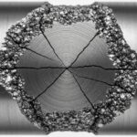
![Close-up of a fractured steel shaft showing metal fatigue beach marks and failure zones.]()
What is Metal Fatigue and How Do Engineers Prevent It?
![Industrial machinery fitted with smart sensors displaying real-time condition-based maintenance data on a digital overlay.]()
What is Condition-Based Maintenance and How Does It Work?