Utility Station
✅ Verified for 2026 by Epcland Engineering Team

Mastering Industrial Utility Station Design for 2026

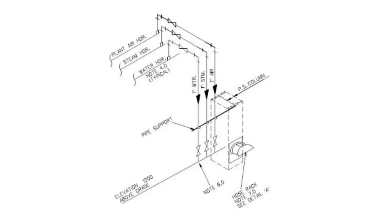
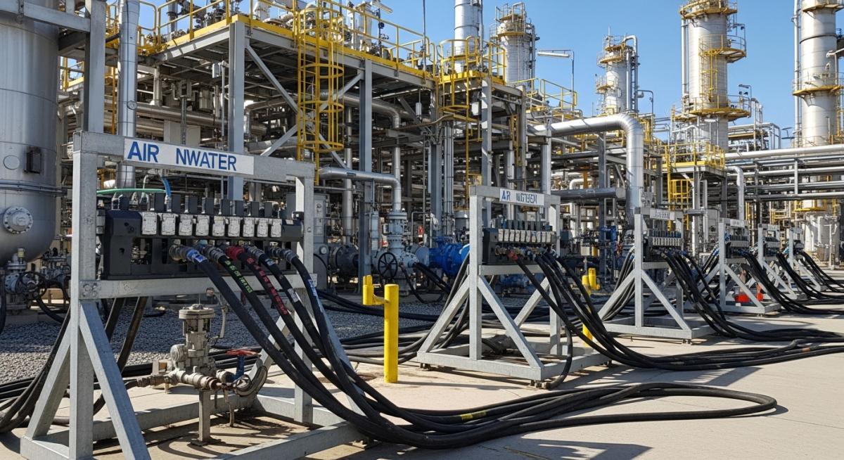
Industrial Utility Station Design is a critical component of modern plant engineering, serving as the centralized distribution point for essential services like steam, air, water, and nitrogen. By strategically placing these stations throughout a facility, engineers ensure that every piece of equipment remains accessible for maintenance, cleaning, and emergency purging operations.

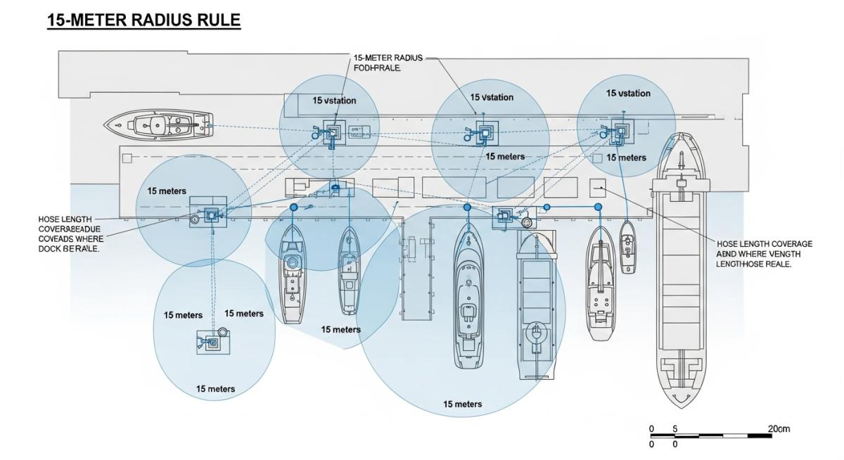
“A utility station is a modular manifold assembly designed to provide localized access to plant utilities. In professional engineering standards, these stations are typically spaced to ensure a 15-meter maximum hose reach to any vessel or instrument within the process area.”

Utility Station Competency Quiz

1. What is the standard hose length used to determine the spacing in Industrial Utility Station Design?

Understanding Utility Station Fundamentals

As of 2026, Industrial Utility Station Design remains the backbone of localized plant maintenance. These stations are strategically placed throughout an industrial facility to supply essential utilities to various equipment and vessels. The distribution of these stations is governed by the "Radius of Access" rule, which ensures that any vessel can be efficiently serviced using hoses of typically 15 meters in length. Proper layout and installation are vital to ensure that utilities are safely provided to every corner of the plant.

Standard Types of Utilities

N2

Nitrogen

An inert gas primarily used for purging services. It is critical to ensure all nitrogen is removed before maintenance personnel enter a vessel to prevent asphyxiation due to oxygen displacement.

PA

Plant Air

Serves multiple cleaning purposes, including shell and tube heat exchanger tubes and tanks. High-pressure air effectively removes debris to maintain equipment cleanliness.

SW

Service Water

Essential for general cleaning tasks within the plant. Used for washing heat exchangers, floors, and vessels to ensure the plant remains in optimal operational condition.

STM

Steam

Utilized for cleaning vessels, heating parts, and de-clogging heat exchanger tubes. Its high temperature makes it an effective cleaning agent for heavy industrial applications.

🎥 Featured Engineering Resource

Fittings and Hose Connection Standards

In 2026, the reliability of Industrial Utility Station Design depends heavily on the standardization of fittings. Precise connection types ensure that maintenance personnel do not cross-contaminate lines and can respond rapidly during turnarounds. All branch connections at the manifold feature globe valves for precise throttling and positive isolation.

Manifold Orientation

For safety and ergonomic handling, connections for Air, Water, and Nitrogen are generally directed downward, preventing hose kinking and reducing stress on the couplings.

Valve Standard

Isolation is strictly achieved via Globe Valves. Unlike ball valves, globe valves allow for controlled opening to prevent pressure surges in the utility hoses.

Utility Service Connection Type Hose Material & Specs (2026)
Nitrogen (N2) Quick-type / NRV Rubber construction; 25m length; built-in non-return valve and male quick coupling at pipe end.
Steam (S) Flanged-type Stainless steel braiding; male quick coupling at station end; female threaded end at tool side.
Plant Air (PA) Quick-type Reinforced rubber; male quick connect at station end; male threaded ends at tool side.
Service Water (SW) Quick-type Standard rubber; male quick connect at station end; male threaded ends at tool side.

2026 Safety Note: Never substitute a steam hose with a rubber air/water hose. The thermal degradation of rubber under steam pressure can lead to catastrophic hose failure. Always verify the stainless steel braiding on steam lines before commissioning.

The Critical Role of Isolation Valves in Utility Stations

In the high-pressure environment of a 2026 industrial facility, safety and efficiency are non-negotiable. A cornerstone of Industrial Utility Station Design is the strategic placement of isolation valves. These valves, positioned nearest to the main header, serve as primary safeguards against mechanical failure and are essential for maintaining operational continuity during localized emergencies.

Guarding Against Line Rupture

Imagine a scenario where a technician accidentally overstresses a utility hose station specification coupling. A sudden "SNAP" occurs near ground level—a zone active with personnel. Without an immediate isolation valve, the entire plant header might depressurize, forcing a total unit shutdown and creating an immediate asphyxiation or thermal hazard.

Immediate Containment

Strategic valve placement allows for the immediate shutdown of an affected section without disrupting the entire plant’s operation. This "modular isolation" is a key requirement in 2026 safety audits.

Ergonomic Accessibility

By placing valves near grade level, maintenance crews can operate services without climbing into the pipe rack. This accessibility reduces the risk of falls and significantly improves turnaround efficiency.

Placement & Spatial Distribution

To achieve the 15-meter coverage rule effectively, Industrial Utility Station Design dictates specific physical locations for manifold mounting:

  • Pipe-Rack Columns: Primary mounting points for main distribution.
  • Elevated Structures: Essential for multi-level technological structures where vessels are stacked.
  • Operating Platforms: Localized stations for vertical equipment and reactors.
  • Loading Racks: High-frequency zones requiring dedicated utility access.

Note: In 2026, the 15-meter radius is considered the "Golden Rule" for utility station piping layout optimization to ensure no equipment is left out of reach.

Core Principles of Industrial Utility Station Design

The engineering logic behind Industrial Utility Station Design is governed by both operational efficiency and stringent safety codes. Most international EPC projects follow ASME B31.3 for piping and API recommended practices for utility distribution. The primary objective is to provide a reliable source of Nitrogen, Plant Air, Service Water, and Steam within a 15-meter radius of any maintenance point.

Industrial Utility Station Design 4-Service Header for Refinery Plants 2026

Figure 1: Standard 4-Service Manifold Configuration for 2026 Facilities.

Physics of Utility Distribution

When calculating the utility station piping layout, engineers must account for pressure drops across the hose. For instance, in a plant air vs service water station comparison, the compressibility of air necessitates larger header diameters to maintain terminal pressure.

Basic Utility Flow Formula

To ensure sufficient flow at the nozzle, the pressure (P) at the station must exceed the required equipment pressure plus the friction loss (delta P) of the 15m hose:

P(station) > P(tool) + delta P(hose)

*Calculated based on 2026 friction factor standards for reinforced rubber hoses.

Standard Utility Hose Station Specifications

Detailed utility hose station specifications involve more than just pipes. Each service branch must include an isolation valve, a check valve (to prevent backflow/contamination), and a quick-disconnect coupling. For steam, a steam trap and strainer are essential to protect the integrity of the station.

Utility station piping layout and spacing diagram showing 15m hose reach

Figure 2: Spatial Coverage Diagram illustrating the 15-meter coverage radius.

Utility Service Line Size (Typ.) Pressure (Barg) Primary Application
Nitrogen (N2) 1 inch 7.0 Vessel Purging / Inerting
Plant Air (PA) 1 inch 7.0 - 8.5 Pneumatic Tools / Cleaning
Service Water (SW) 1 inch 4.5 Equipment Washdown
LP Steam (S) 3/4 inch 3.5 Thermal Cleaning / Steaming

In any Piping and Instrumentation Diagram (P&ID) for utility stations, the sequence of valves is strictly defined to ensure nitrogen purging safety protocols are met. For example, the nitrogen line must never be cross-connected with the plant air line without a double-block-and-bleed arrangement to prevent accidental asphyxiation in the air system.

Design Considerations and Risk Mitigation

In 2026, Industrial Utility Station Design must evolve beyond simple pipe routing to address the dynamic nature of high-density plant environments. Addressing challenges such as accessibility and hardware degradation proactively prevents costly downtime and enhances the overall safety culture of the facility.

Accessibility

Stations must be accessible to all primary equipment. Optimal utility station piping layout minimizes transit time for technicians, directly improving operational efficiency.

Safety Protocols

Prioritize nitrogen purging safety protocols. Design must include high-visibility signage and physical locks to prevent unauthorized use of inert gases.

Integrity Checks

Regular inspection of utility hose station specifications is crucial. Monitoring valves and connectors for micro-leaks ensures long-term reliability.

Common Challenges and 2026 Solutions

1. Wear and Tear on Hoses

Hoses transporting steam, water, and nitrogen degrade due to harsh chemicals, extreme temperatures, and mechanical stress. In 2026, the standard solution involves utilizing stainless steel braiding for steam and reinforced polymers for air, preventing pressure drops and catastrophic failure.

Solution

Scheduled 6-Month Integrity Testing

2. Traffic and Machinery Risks

Utility stations are often positioned in high-traffic zones. The risk of machinery striking a utility hose station is significant. Modern designs incorporate protective bollards and "hose saddles" to keep lines off the ground, reducing trip hazards and accidental line breaks.

Solution

Bollard Protection & Hose Racks

By addressing these Industrial Utility Station Design challenges proactively, plant owners can prevent costly maintenance downtime while fostering a safer work environment for personnel.

Engineering Solutions for 2026 Utility Station Longevity

Effective Industrial Utility Station Design must incorporate proactive solutions to mitigate the physical and operational stresses of a high-capacity plant. By focusing on material science and strategic hardware placement, engineers can ensure that utility hose station specifications remain compliant with 2026 safety standards throughout the equipment's lifecycle.

1. High-Quality Material Integration

Durable Hose Materials

Selecting the correct utility hose station specifications is vital. For 2026, stainless steel-braided hoses are the industry standard for steam services, while reinforced rubber hoses provide the necessary elasticity for air and water.

Robust Fittings

All couplings and connections should utilize carbon steel or stainless steel. High-quality metal fittings significantly reduce the risk of thread stripping and localized leaks under high pressure.

Maintenance Tip: Implement a computerized routine inspection schedule to detect early signs of corrosion or "bird-caging" in braided hoses before they lead to failure.

2. Strategic Valve Placement & Protection

  • VALVE
    Isolation Valves at Grade Level Facilitates rapid emergency response and prevents total system depressurization during a hose break.
  • GUARD
    Protective Barriers & Signage Installation of physical bollards absorbs machinery impact, while clear service-type labels ensure nitrogen purging safety protocols are visually reinforced.
  • REEL
    Flexible Support Systems Using hose reels or wall-mounted brackets keeps service water and air lines off the ground, eliminating tripping hazards and abrasive wear from dragging.

Case Study: Industrial Utility Station Design Failure Analysis

During a major 2026 refinery maintenance turnaround, a facility experienced significant delays due to poor Industrial Utility Station Design. The project aimed for a 14-day shutdown, but initial assessments showed that maintenance teams were losing 4 hours per shift simply managing hose extensions. This analysis explores how optimizing station density and steam utility station requirements saved the project timeline.

Refinery maintenance turnaround utility station optimization for 14-day shutdown

Figure 3: Optimized Utility Manifold Deployment in the 2026 Turnaround Phase.

Project Metadata

Location: Gulf Coast Refining Complex
Equipment: 12 Crude Distillation Columns
Conditions: 14-Day High-Intensity Shutdown
Utility Focus: High-Volume Nitrogen Purging

The Problem: Spatial Inefficiency

The original 1990s utility station piping layout relied on a 30-meter radius, forcing technicians to daisy-chain multiple hoses. This caused a 15% drop in plant air pressure and created severe tripping hazards. More critically, the nitrogen purging safety protocols were compromised as the long hose runs increased the risk of leaks in congested scaffolding areas.

The Engineering Solution

The engineering team implemented a "Zero-Extension" policy by installing 14 temporary modular utility stations. These were designed based on the 2026 utility hose station specifications, ensuring:

  • Strict 15-meter coverage for every manway and heat exchanger bundle.
  • Color-coded manifolds (Yellow for Air, Blue for Water, Green for Nitrogen, Silver for Steam).
  • Integrated flow meters to monitor nitrogen consumption during the critical 48-hour purging window.

Results & ROI (2026 Data)

The redesign led to a measurable increase in efficiency:

22% Reduction in Purge Time
0 Hose-related Incidents
$1.2M Estimated Labor Savings

Conclusion: Strategic utility station placement is not just a convenience; it is a critical path driver for industrial turnarounds.

Engineering FAQ: Industrial Utility Station Design

How do utility hose station specifications differ for hazardous areas?
In hazardous zones, utility hose station specifications must include anti-static (conductive) hoses and non-sparking quick-connect couplings. Furthermore, the station structure must be grounded to prevent static discharge during high-velocity fluid transfer.
What are the critical nitrogen purging safety protocols for 2026?
Current nitrogen purging safety protocols mandate the use of oxygen deficiency monitors at every utility station. Additionally, nitrogen hoses must be distinctively labeled with tactile warnings to prevent accidental use as breathing air or plant air.
How is the steam utility station requirements met for cleaning?
To meet steam utility station requirements, the branch must include a thermal insulation jacket for operator protection and a local pressure gauge. The manifold is typically pitched toward a steam trap to ensure dry steam is available for effective equipment cleaning.
Where can I find the Piping and Instrumentation Diagram (P&ID) for utility stations?
The standard Piping and Instrumentation Diagram (P&ID) for utility stations is found in the project's "Standard Drawings" or "Utility Distribution" section. For 2026 projects, these are often integrated into Digital Twin platforms, allowing maintenance teams to locate the nearest station via mobile handhelds.

Optimizing Industrial Assets for 2026

Superior Industrial Utility Station Design is the backbone of safe and efficient plant operations. By adhering to the 15-meter rule and integrating high-quality manifolds, engineering firms can significantly reduce maintenance downtime and improve safety outcomes.

#PipingEngineering #PlantDesign2026 #UtilityManifolds