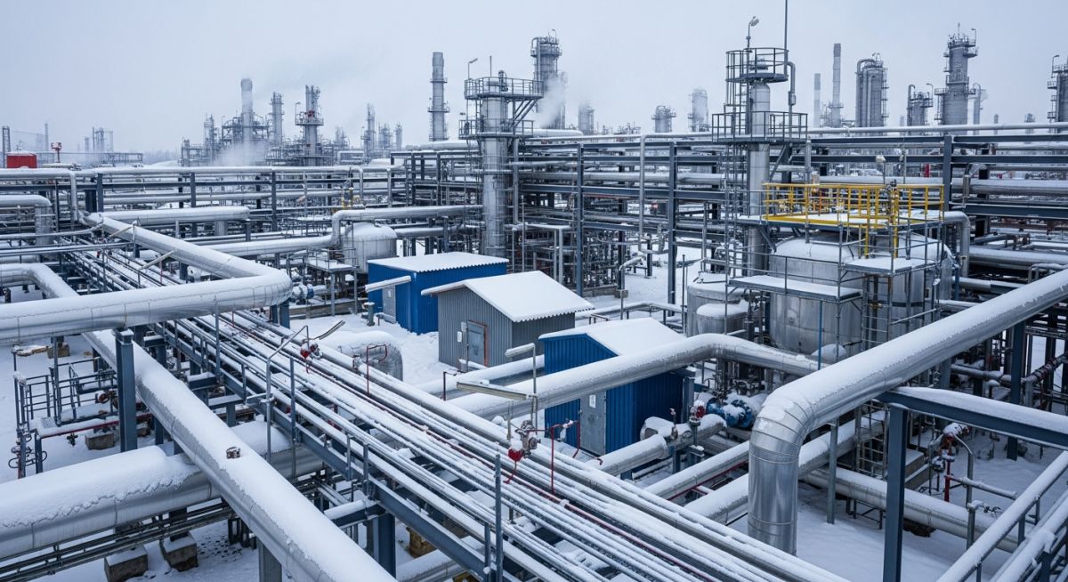
What is Winterization? Requirements for Winterization System Design
In my 20-plus years of managing piping systems in some of the harshest sub-zero environments on earth, I have seen firsthand what happens when winterization is treated as an afterthought. I have stood on-site in northern Alberta at minus forty degrees Celsius, watching a multi-million dollar process plant grind to a complete halt because a single un-traced impulse line froze solid, sending false pressure signals to the safety instrumented system. Winterization is not merely about wrapping pipes in fiberglass insulation; it is a rigorous, multi-disciplinary engineering discipline. It demands a deep understanding of thermodynamics, fluid behavior, and mechanical design to ensure that a plant remains safe, operational, and structurally sound when the mercury plummets.
- Understand the critical distinction between freeze protection (preventing phase change) and temperature maintenance (preserving process viscosity).
- Master the core heat loss calculations required to size insulation and electric or steam heat tracing systems.
- Learn how to design robust physical layouts that leverage natural drainage, dead-leg elimination, and structural windbreaks.
- Implement field-proven verification checklists to guarantee system reliability before the first freeze hits.
Core Principles of Winterization System Design in Cold Climates
The physics of freezing in piping is straightforward yet unforgiving. When static fluids—especially water, aqueous solutions, or high-pour-point hydrocarbons—lose heat to the cold ambient air, their temperature drops. If it falls below the freezing or pour point, phase change or solidification occurs, leading to line blockages, overpressure, and catastrophic pipe ruptures. To prevent this, we must balance the heat loss from the pipe with the heat supplied by active systems, or slow down the heat loss using passive insulation.
Heat loss from an insulated pipe can be calculated using steady-state radial heat transfer. The fundamental formula for heat loss per unit length of pipe is:
Where:
Q = Heat loss rate (Watts)
k = Thermal conductivity of the insulation material (W/m-K)
L = Length of the pipe (meters)
T_p = Process fluid temperature (Celsius)
T_a = Minimum ambient design temperature (Celsius)
D_i = Inside diameter of insulation / Outside diameter of pipe (meters)
D_o = Outside diameter of insulation (meters)
h_c = Combined convective and radiative heat transfer coefficient of the outer surface (W/m2-K)
In my experience, wind speed is the most overlooked variable in this equation. A 40 km/h wind can increase the convective heat transfer coefficient by a factor of three compared to still air, rapidly accelerating heat loss. Therefore, we always design for the worst-case local wind conditions, not just static ambient temperatures.
Never assume insulation alone will prevent freezing in a static line. Insulation only slows down the rate of heat loss; it does not add heat. If a water line remains static long enough in sub-zero temperatures, it will freeze regardless of insulation thickness. Active heat tracing is mandatory for static or low-flow systems.
We categorize winterization into two primary methods:
- Passive Winterization: Thermal insulation (mineral wool, calcium silicate, cellular glass) and physical enclosures.
- Active Winterization: Heat tracing (Electric Heat Tracing – EHT, Steam Tracing, or Glycol Tracing).
For design limits and compliance, we refer to ASME B31.3 for piping design limits, ISO 12241 for thermal insulation calculations, and API RP 555 for instrumentation piping.
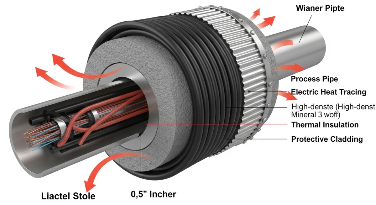
Selecting the correct winterization method depends heavily on the minimum ambient design temperature and the fluid properties. The table below outlines standard engineering recommendations for various temperature ranges.
| Min Ambient Temp Range (°C) | Fluid Type | Recommended Method | Insulation Thickness (mm) | Engineering Notes |
|---|---|---|---|---|
| 0 to -10 °C | Utility Water, Condensate | Insulation Only (Continuous Flow) or EHT | 25 – 50 | Ensure no dead legs exist in the piping layout. |
| -10 to -25 °C | Process Water, Hydrocarbons | Electric Heat Tracing (EHT) + Insulation | 50 – 75 | Self-regulating cables are preferred for safety. |
| -25 to -45 °C | All Aqueous Fluids, Heavy Oils | Steam Tracing or High-Output EHT | 75 – 100 | Critical for instrument impulse lines and manifolds. |
| Below -45 °C | Arctic Conditions (All Fluids) | Glycol/Water Tracing or Dual EHT | 100 – 150 | Enclosures required for control valves and transmitters. |
This matrix maps core technical entities, structural acronyms, physical parameters, and hyperlinked standard references used in winterization system design.
| Entity / Acronym | Technical Description | Key Physical Parameter | Applicable Standard Reference |
|---|---|---|---|
| EHT (Electric Heat Tracing) | Use of resistive heating cables to maintain pipe temperature | Power Output (W/m), Sheath Temp | IEEE 515 |
| SST (Steam Skin Tracing) | External steam tubes run parallel to process piping | Steam Pressure (barg), Saturation Temp | API RP 555 |
| Dead-Leg | Non-flowing section of a piping system prone to freezing | Length-to-Diameter Ratio (L/D) | ASME B31.3 |
| Cellular Glass | Rigid, impermeable insulation material resistant to moisture | Thermal Conductivity (k = 0.04 W/m-K) | ASTM C552 |
Site Verification Protocols for Winterization Systems
Before the winter season begins, a comprehensive field walkdown is mandatory. In my experience, minor installation errors—such as a torn vapor barrier or an uninsulated valve flange—are the primary causes of localized freezing. Use this checklist to verify your winterization system design integrity.
-
Heat Tracing Continuity: Verify electrical resistance (megger test) of all EHT circuits in accordance with IEEE 515.
-
Thermostat Calibration: Confirm ambient-sensing and line-sensing thermostats are calibrated to the correct setpoints (typically 4°C for freeze protection).
-
Insulation Weather Barrier: Inspect the aluminum or stainless steel cladding for tight seals. Water ingress destroys the thermal efficiency of insulation.
-
Valve and Flange Covers: Ensure removable insulation blankets are installed on all valves, flanges, and inline instruments requiring maintenance.
-
Low-Point Drains: Verify that all utility and process low points have functional drain valves to allow complete system dry-out during shutdowns.
-
Steam Trap Functionality: Check that steam tracing traps are discharging condensate properly without backing up steam lines.
Field Case Study: Real-World Application
During an extreme winter vortex in North Dakota, a petrochemical facility experienced a complete shutdown of its sulfur recovery unit. The ambient temperature dropped to -38°C with wind gusts up to 60 km/h. The primary cause was the freezing of the instrument air supply lines and several liquid sulfur run lines. The existing winterization system relied on low-pressure steam tracing. However, due to poor insulation cladding installation, water had penetrated the mineral wool insulation, turning it into a thermal conductor rather than an insulator. To make matters worse, several steam traps had failed in the closed position, causing condensate to back up and freeze inside the tracer tubes, which subsequently ruptured.
I was brought in to lead the root-cause analysis and redesign the winterization system. We stripped the damaged mineral wool and replaced it with impermeable cellular glass insulation conforming to ASTM C552, which prevents water absorption. We replaced the unreliable steam tracing on the critical instrument lines with self-regulating Electric Heat Tracing (EHT) monitored by a centralized control system. For the sulfur lines, we redesigned the steam tracing circuits, reducing the run lengths and installing smart thermodynamic steam traps with wireless failure transmitters. The following winter, despite similar sub-zero conditions, the plant achieved 100% operational uptime with zero freeze-related incidents.
Direct Recommendation: Always specify non-wicking, impermeable insulation like cellular glass for areas prone to moisture ingress, and transition critical instrument lines from steam to electric heat tracing for precise temperature control.
Key Standards for Winterization System Design
What is the difference between freeze protection and temperature maintenance?
Which insulation material is best for cold-climate piping?
How do you determine the required heat tracing wattage?
Can we use steam tracing for all winterization applications?
What is a ‘dead-leg’ and why is it dangerous in winter?
How does wind speed affect winterization design?
Complete Course on
Piping Engineering
Check Now
Key Features
- 125+ Hours Content
- 500+ Recorded Lectures
- 20+ Years Exp.
- Lifetime Access
Coverage
- Codes & Standards
- Layouts & Design
- Material Eng.
- Stress Analysis