What is a 3D Point Cloud? Tools, Features, and Engineering Applications

You are standing in the middle of a 40-year-old offshore platform, tasked with installing a new 12-inch high-pressure gas line. The original “as-built” drawings haven’t been updated since 1986. If you rely on those blueprints, your fabrication will clash with three different structural beams and a firewater line. How do you map this chaotic 3D reality into your CAD software with millimeter precision?
The answer is the 3D Point Cloud—the digital bridge between physical existence and virtual engineering.
Core Knowledge Brief
- Precision Acquisition: Learn how LiDAR and Photogrammetry generate millions of XYZ coordinates to form a 3D Point Cloud.
- Engineering Integration: Discover how point clouds eliminate manual measurement errors in ASME B31.3 piping and BIM workflows.
- Digital Twins: Understand why the 3D Point Cloud is the non-negotiable foundation for 2026 industrial digital twins.
Quick Definition: What is a 3D Point Cloud?
A 3D Point Cloud is a high-density collection of individual data points located in a three-dimensional coordinate system (X, Y, and Z). Generated via laser scanning or photogrammetry, these points represent the external surfaces of objects or environments, providing a highly accurate digital “as-built” replica for engineering analysis and CAD modeling.
“In my 20 years of field engineering, the shift from tape measures to 3D Point Cloud technology is the single biggest risk-mitigator I have seen. It transforms ‘guessing’ on-site into ‘verifying’ in the office, saving millions in rework costs.”
— Atul Singla, Founder of Epcland
Table of Contents
Complete Course on
Piping Engineering
Check Now
Key Features
- 125+ Hours Content
- 500+ Recorded Lectures
- 20+ Years Exp.
- Lifetime Access
Coverage
- Codes & Standards
- Layouts & Design
- Material Eng.
- Stress Analysis
Engineering Knowledge Check
Test your expertise on 3D Point Cloud technology and applications.
1. Which data component is mandatory for a basic 3D Point Cloud file?
1. The Fundamental Physics: Generation of a 3D Point Cloud
The creation of a 3D Point Cloud is a process of rapid spatial sampling. In 2026, the technology has evolved from simple distance measurements to complex light-field captures. At its core, a point cloud is generated by measuring the distance from a known sensor location to a physical surface. By repeating this measurement millions of times per second across a 360-degree field of view, the system populates a virtual environment with XYZ coordinates. These points collectively define the “skin” of the scanned object, providing an incredibly dense and accurate representation of its geometry.
Precision Laser Scanners for 3D Point Cloud Acquisition
Terrestrial Laser Scanning (TLS) remains the gold standard for high-accuracy engineering. These devices use LiDAR (Light Detection and Ranging) technology, specifically Time-of-Flight or Phase-Shift methods. A laser pulse is emitted, hits a surface, and returns to the sensor. The device calculates the time elapsed to determine distance. Modern 2026 scanners, such as those used in EPC projects, can capture up to 2 million points per second with a range accuracy of ±1mm. This density is critical when capturing small-bore piping or intricate structural connections where a “sparse” cloud would fail to provide enough detail for fabrication-ready models.
Industrial Photogrammetry: Synthesizing 3D Point Cloud Data
While LiDAR uses active light, photogrammetry is a passive technique that synthesizes a 3D Point Cloud from overlapping high-resolution digital photographs. By identifying “keypoints” shared between multiple images taken from different angles, sophisticated Structure-from-Motion (SfM) algorithms calculate the 3D position of those points in space. In 2026, industrial photogrammetry is often fused with LiDAR data to provide high-fidelity RGB (color) mapping, allowing engineers to visually distinguish between different materials, such as identifying a galvanized steel pipe versus a painted carbon steel line within the same 3D Point Cloud.
2. Technical Features and Data Density of the 3D Point Cloud
Understanding the technical “DNA” of a 3D Point Cloud is essential for managing large-scale engineering datasets. Every point in the cloud is more than just a dot; it is a data packet containing specific attributes that define the physical world.
- Spatial Accuracy (XYZ): The primary feature. Every point is registered to a local or global coordinate system, allowing for direct measurement of distances, angles, and volumes within the 3D Point Cloud environment.
- Intensity Values: This represents the strength of the laser pulse return. Different materials reflect light differently; for example, a reflective safety sign will have a much higher intensity value than a matte black rubber hose. This allows engineers to “see” textures even without color data.
- RGB Mapping: Color data applied to the points from integrated cameras. This transforms a gray-scale geometric model into a photorealistic digital twin, which is vital for remote site inspections and safety training.
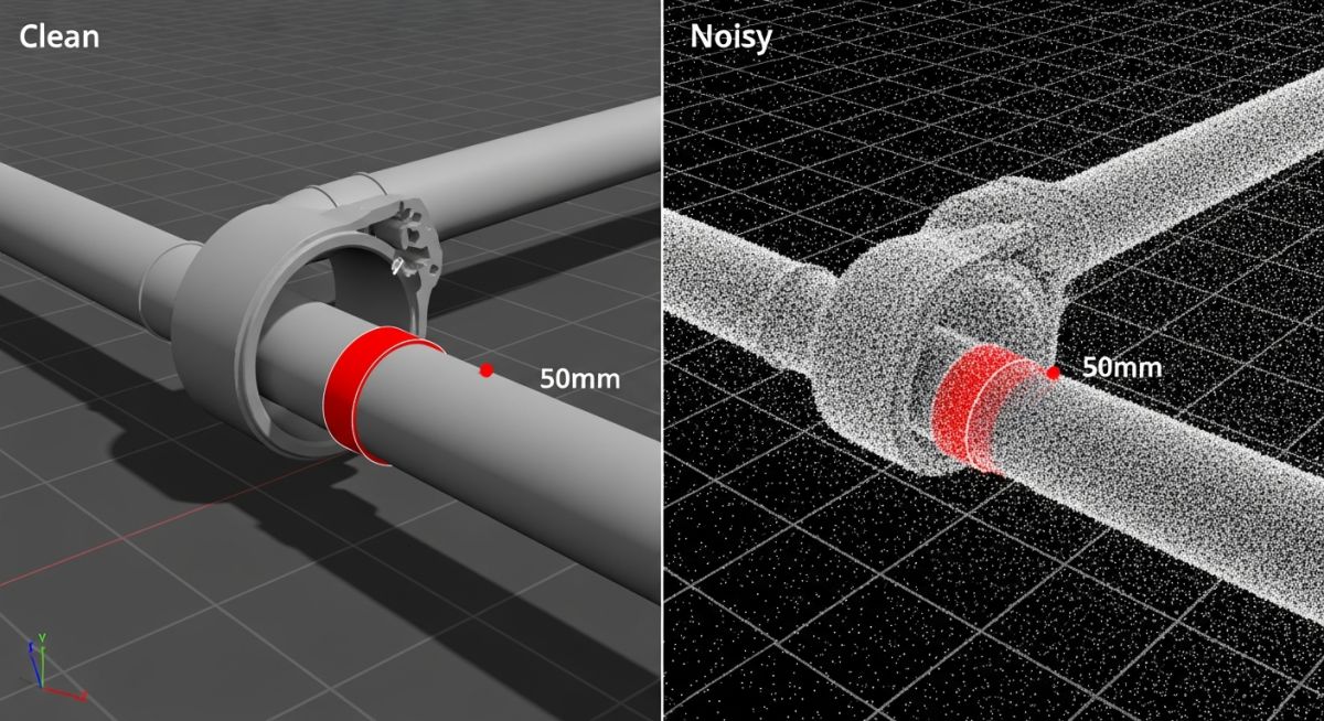
- Point Density: Measured in points per square meter (pts/m2) or average point spacing. Higher density allows for the detection of smaller defects, such as corrosion pitting or structural hairline cracks.
In the context of 2026 standards, the “intelligence” of a 3D Point Cloud has shifted toward semantic enrichment. Software now uses AI to automatically classify points—distinguishing a “pipe” point from a “floor” point—vastly reducing the manual labor involved in turning raw data into actionable CAD entities.
3. High-Value Engineering Applications of 3D Point Cloud
In 2026, the utilization of 3D Point Cloud data has moved beyond simple visualization. It is now a critical input for high-stakes engineering calculations and compliance audits. By providing a 1:1 digital replica of physical assets, point clouds eliminate the “assumption gap” that often leads to catastrophic field clashes and schedule overruns.
Integration with ASME B31.3 Piping Design
For brownfield projects involving ASME B31.3 process piping, a 3D Point Cloud is indispensable. Engineers use the cloud to perform “clash detection” before a single pipe is fabricated. By overlaying the proposed 3D CAD model onto the point cloud of the existing facility, designers can identify interferences with millimeter precision. This ensures that new spools fit perfectly into existing flanges, maintaining the structural integrity and safety standards required by global piping codes.
As-Built Documentation for Digital Twins
The 3D Point Cloud serves as the foundational layer for the 2026 Digital Twin. Unlike static 2D drawings, a point cloud captures the “as-is” condition, including pipe sagging, structural deformations, and temporary modifications that are rarely documented. This high-fidelity data allows for real-time asset management and predictive maintenance, where sensors on the physical plant are mapped directly to their digital coordinates in the cloud.
| Feature / Method | Terrestrial Laser (LiDAR) | Mobile Mapping (SLAM) | Photogrammetry |
|---|---|---|---|
| Relative Accuracy | 1mm – 3mm (Highest) | 10mm – 30mm | 5mm – 20mm |
| Acquisition Speed | Stationary / Slow | Walking Speed (Fastest) | Variable (Depends on Images) |
| Best Use Case | Complex Piping / Flanges | Large Warehouses / Tunnels | Stockpiles / Façades |
| Data Complexity | Very High Density | Medium Density | High (Texture Rich) |
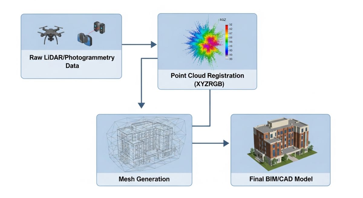
4. Processing and Registration: Refining the 3D Point Cloud
Raw data from a scanner is rarely usable in its initial state. The processing phase involves Registration, where multiple scans from different vantage points are stitched together. In 2026, this is predominantly achieved through “Cloud-to-Cloud” registration, which uses geometric overlaps to align datasets without the need for physical targets.
Standardization Note
Industry leaders now adhere to ISO 19650 for BIM data management, ensuring that 3D Point Cloud files are properly georeferenced and indexed for long-term project lifecycle use.
Following registration, the cloud undergoes Thinning (to reduce file size for CAD performance) and Cleaning (to remove “noise” such as birds, steam, or moving personnel). The final output is a unified, clean 3D Point Cloud ready for export to formats like .E57, .RCP, or .LAS.
3D Point Cloud Data & Storage Estimator
Estimate the raw data footprint and required scan positions for your engineering project (2026 Standards).
Estimated Technical Requirements
Note: Estimates assume terrestrial LiDAR scanning with 30% overlap for registration. Actual data sizes may vary based on 2026 sensor efficiency and RGB encoding.
Don’t miss this video related to Piping Engineering

Summary: In this video, let’s explore the types & Scope of piping engineers. In general, Piping engineers can be categorized into the ……
3D Point Cloud Failure Case Study: Rectifying Scan Misalignment
The Scenario
In early 2026, a major chemical processing plant initiated a brownfield expansion. The project required the insertion of a new heat exchanger into a tightly packed pipe rack. The survey team provided a 3D Point Cloud generated via mobile SLAM scanning. However, during the CAD modeling phase, the piping lead noticed that horizontal runs appeared to have a 3-degree “slope” that did not exist in reality.
The Failure
The failure was traced to registration drift. Because the mobile scanner relied on “SLAM” (Simultaneous Localization and Mapping) without survey-grade control points, errors accumulated over the 200-meter long rack. The resulting 3D Point Cloud was “bent,” making the digital twin useless for precision fabrication.
The 2026 Resolution
The engineering team implemented a Hybrid Acquisition Strategy:
- Control Framework: Established 10 survey-grade “checkerboard” targets using a Total Station.
- Targeted Re-scan: Re-scanned critical tie-in points using Terrestrial LiDAR (Phase-Shift) to anchor the cloud.
- Cloud-to-Cloud Refinement: Used 2026 AI-driven registration software to “tighten” the SLAM data against the fixed survey targets.
Expert Insights: Lessons from 20 years in the field
“Transitioning to a 3D Point Cloud workflow isn’t just about buying a scanner; it is about changing your engineering philosophy.”
- 01. Trust the Cloud, Not the Drawing: In 2026, the point cloud is the only ‘source of truth.’ If a legacy drawing says a pipe is 4 inches but the cloud measures 4.5 inches (including insulation), trust the cloud.
- 02. Data Management is Engineering: A 500GB 3D Point Cloud is useless if your workstation can’t open it. Always include a ‘Thinning’ and ‘Web-view’ strategy in your project execution plan.
- 03. Hybrid Scanning: Don’t rely on one tool. Use LiDAR for high-accuracy flanges and Photogrammetry for overall site context and texture.
Pro-Tip for 2026
Always request E57 format for raw data exchange. It is the vendor-neutral standard that preserves your 3D Point Cloud metadata, intensity, and color across different CAD platforms like AutoCAD, Revit, and AVEVA.
Frequently Asked Questions
What is the file size of a typical 3D Point Cloud? ▼
Can I convert a 3D Point Cloud directly to CAD? ▼
How accurate is a 3D Point Cloud in 2026? ▼
Why is my 3D Point Cloud showing “ghost” images? ▼
Is LiDAR better than Photogrammetry for point clouds? ▼
Does rain affect 3D Point Cloud quality? ▼
References & Standards
📚 Recommended Resources: Piping Engineering
Read these Guides
🎓 Advanced Training


Related posts:
![High-grade industrial Wing Nut Types and Applications for mechanical assemblies.]()
Wing Nut Types and Applications: The 2026 Engineering Guide
![Industrial Monorail Crane Systems installed in a modern manufacturing plant 2026.]()
Monorail Crane Systems: Design, Types & 2026 Standards Guide
![Lead engineer performing a Factory Acceptance Test FAT on an industrial skid system 2026]()
Factory Acceptance Test FAT: The 2026 Engineering Guide to Zero-Defect Delivery
![Professional engineering workspace showing a Basis of Design document layout for a 2026 project.]()
Basis of Design: How to Write a BOD for Engineering Projects in 2026
![Industrial Flare Knockout Drum Sizing and installation in a refinery relief system.]()
Flare Knockout Drum Sizing: Design & API 521 Standards (2026 Guide)
![Advanced Reboiler Control Systems in a modern petrochemical refinery 2026.]()
Reboiler Control Systems: Engineering Guide to Precision Control 2026


