Valve Packing Engineering Guide: Materials, Types, and Sealing Technology 2026
In modern piping systems, Valve Packing is the primary sealing mechanism used to prevent fluid from escaping the valve body along the stem. Often housed within a specialized chamber known as a stuffing box, high-performance Valve Packing must maintain a tight seal under varying pressures and temperatures while minimizing friction to allow for smooth valve actuation.
Quick Definition: What is Valve Packing?
Valve Packing is a contact-style dynamic seal consisting of deformable materials or pre-formed rings compressed around a valve stem. Its critical engineering function is stem seal leakage prevention, ensuring that hazardous or high-pressure process fluids remain contained while the stem rotates or moves axially during operation.
Table of Contents
Engineering Knowledge Check: Valve Packing
Complete Course on
Piping Engineering
Check Now
Key Features
- 125+ Hours Content
- 500+ Recorded Lectures
- 20+ Years Exp.
- Lifetime Access
Coverage
- Codes & Standards
- Layouts & Design
- Material Eng.
- Stress Analysis
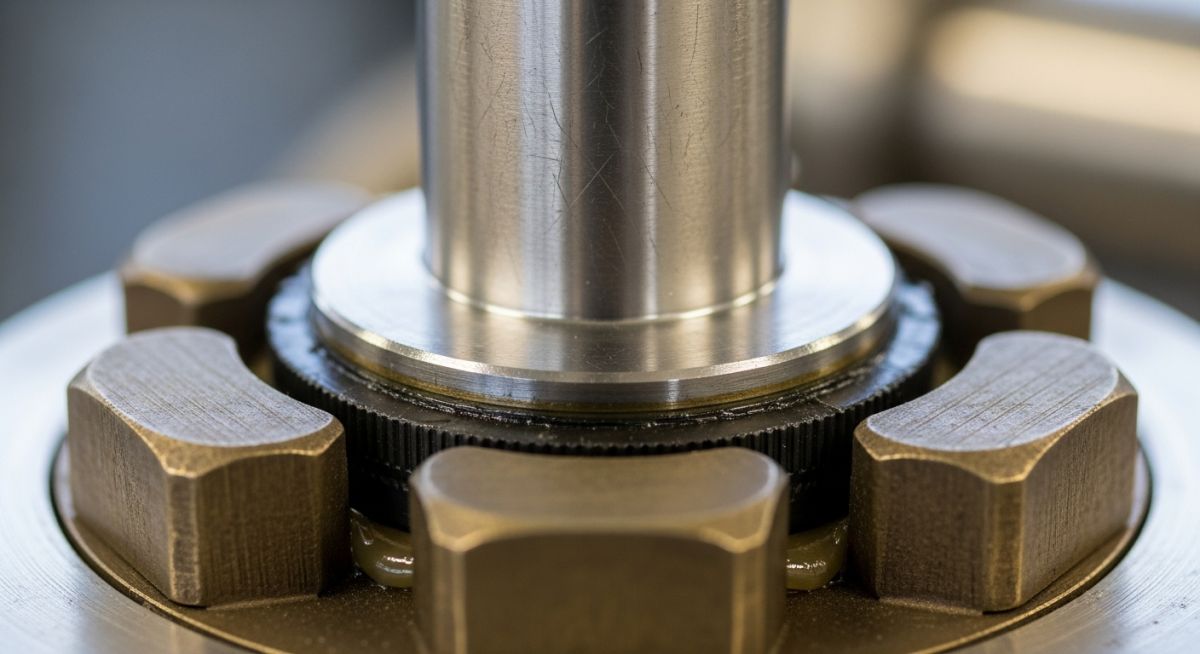
Anatomy of the Valve Packing Assembly
The valve packing assembly is a sophisticated arrangement of stationary seals and mechanical components located in the valve bonnet. To achieve effective Stem seal leakage prevention, each part of the assembly must work in unison to maintain a constant radial pressure against the valve stem while resisting the axial force of the process fluid.

Figure 1: Standard cross-section of a valve stuffing box featuring a lantern ring and gland follower.
Sealing Elements: Packing Rings and Chevron Sets
The core of the assembly is the packing stack, which usually consists of several individual Packing Rings. These rings are designed to deform under axial compression, expanding radially to fill the gap between the stem and the stuffing box wall.
- Compression Rings: Standard square-cross section rings made of braided fibers or graphite.
- Chevron Sets (V-Rings): Shaped like a “V,” these rings use the fluid pressure itself to help flare the lips against the sealing surfaces, making them highly effective for high-pressure Fugitive emissions control.
- Anti-Extrusion Rings: Positioned at the top and bottom of the stack to prevent the softer sealing material from being squeezed out through the clearances.
Compression Components: Gland, Nut, and Gland Follower
To activate the seal, mechanical force must be applied to the packing rings. This is achieved through the following hardware:
- Packing Gland (Follower): A metal sleeve that slides into the stuffing box and rests directly on top of the packing stack.
- Gland Bolts and Nuts: These provide the necessary torque. As the Packing Gland Nut is tightened, it pushes the follower deeper into the stuffing box, compressing the rings.
- Gland Flange: The outer plate that holds the bolts in place, ensuring the follower applies even pressure around the stem.
The Lantern Ring: Lubrication and Leak-off
A Lantern Ring is a perforated spacer ring inserted into the middle of the packing stack. It aligns with a port in the side of the stuffing box (the “lantern port”) and serves two critical engineering functions:
1. External Lubrication
In high-friction or high-cycle applications, the lantern ring allows for the injection of grease or oil to lubricate the stem-to-packing interface, extending the life of the seal.
2. Leak-off Collection
For hazardous or toxic fluids, the lantern port can be connected to a recovery system. Any fluid that passes the lower packing rings is safely diverted through the lantern ring before it can escape to the atmosphere.
Technical Material Science: Selecting the Right Seal
The performance of Valve Packing is primarily dictated by its material composition. In 2026, material science has evolved to balance the trade-offs between chemical resistance, thermal stability, and mechanical strength. Understanding the Graphite vs PTFE packing debate is essential for specifying the correct seal for a given process.
Flexible Graphite: High-Temp Superiority
Flexible graphite is the “gold standard” for high-temperature and high-pressure steam service. It is naturally lubricious, self-lubricating, and chemically inert to most media.
- Thermal Range: Stable from -400°F to 850°F in oxidizing atmospheres and up to 5000°F in non-oxidizing environments.
- Sealing Efficiency: Highly conformable, making it excellent for Fugitive emissions control.
- Limitation: It can be susceptible to galvanic corrosion; modern rings often include passive corrosion inhibitors.
PTFE and ePTFE: Chemical Inertia and Low Friction
Polytetrafluoroethylene (PTFE) is used where chemical compatibility is the priority. Expanded PTFE (ePTFE) provides better dimensional stability than standard PTFE.
- Chemical Resistance: Resists almost all industrial chemicals (pH 0-14), excluding molten alkali metals.
- Friction: Extremely low coefficient of friction, reducing the torque required to actuate the valve.
- Limitation: Susceptible to “cold flow” or creep under high pressure and limited to temperatures below 450°F (232°C).
Synthetic Fibers (Carbon and Aramid) for Abrasive Service
When the process fluid contains solids or slurries, softer materials like pure graphite or PTFE may erode. Synthetic fibers like Carbon Fiber or Aramid (Kevlar) provide the mechanical “backbone” needed to resist wear and abrasion in mining or pulp and paper applications.
Key Characteristics of Performance Packing
Engineering Comparison: Valve Packing Material Properties
| Material | Temp. Limit (°F) | pH Range | Friction Coeff. | Application |
|---|---|---|---|---|
| Flexible Graphite | 850°F (Air) | 0 – 14 | Medium | High-Temp Steam / Oil |
| Pure PTFE | 500°F | 0 – 14 | Very Low | Chemical / Pharma |
| Carbon Fiber | 1000°F+ | 0 – 14 | High | Slurries / Abrasives |
| Synthetic Fiber | 500°F | 3 – 11 | Medium | General Utility |
Pressure and Temperature Resistance (P × T Limits)
In engineering design, packing is often rated using the P × T factor. This is the product of the operating pressure (psi) and the operating temperature (°F).
Limit Value = Pressure (P) × Temperature (T)
As pressure increases, the allowable temperature for a material decreases to maintain the integrity of the seal. Exceeding the material’s P × T limit leads to stem seal leakage, material extrusion, and eventual valve failure.
Chemical Compatibility and pH Ranges
Compatibility is measured on the pH scale (0 to 14). While PTFE and Graphite cover the full spectrum, synthetic fibers or lubricants within the packing may be restricted. For instance, some aramid fibers are sensitive to strong acids and bases, limiting their use in aggressive chemical processes.
EPCLand YouTube Channel
2,500+ Videos • Daily Updates
Valve Packing Gland Torque Calculator
Properly tightening the Packing Gland Nut is critical. Under-tightening leads to stem seal leakage, while over-tightening can crush the packing rings or seize the stem. Use this tool to estimate the required torque for your gland bolts based on system pressure and dimensions.
Packing Gland Torque Estimator (2026 Edition)
Engineering Standards: API 622 and Fugitive Emissions
In 2026, the primary driver for Valve Packing selection is environmental compliance. Modern regulations have shifted the focus from merely “stopping a leak” to Fugitive emissions control. Uncontrolled leaks from valve stems account for over 50% of the total fugitive emissions in a typical refinery.
The API 622 Standard Explained
API 622 (Type Testing of Process Valve Packing for Fugitive Emissions) is the definitive industry benchmark. To pass this test, the packing must undergo 1,510 mechanical cycles and 5 thermal cycles (from ambient to 500°F) while maintaining a leakage rate of less than 100 parts per million (ppm). Packing that meets this criteria is often referred to as “Low-E” (Low Emission) packing.
Installation and Maintenance: The “Live-Loading” Revolution
A common cause of Stem seal leakage prevention failure is “packing consolidation”—where the packing rings lose volume over time due to wear and thermal cycling, leading to a loss of compressive load.
Live-Loading Spring Systems
To combat consolidation, engineers use Live-loading spring systems. This involves placing a stack of Belleville (conical) spring washers on the gland bolts. These springs act as an energy reservoir, maintaining a constant force on the Gland Follower even as the packing wears down or shifts.
Proper Installation Steps for 2026:
- Clean the Stuffing Box: Remove all traces of old packing. Scratches on the stem or box wall will cause immediate leaks.
- Inspect the Stem: The stem finish should ideally be between 8 and 16 RMS. Too rough, and it shreds the packing; too smooth, and it won’t hold the necessary lubricant.
- Stagger the Joints: If using cut rings, stagger the joints by 90 or 120 degrees to prevent a direct “leak path” through the stack.
- Incremental Tightening: Tighten the Packing Gland Nut to 25%, 50%, 75%, and then 100% of the target torque, cycling the valve between each step.
Case Study: Valve Packing Failure & Emission Control
Field Engineering Report | Case Ref: EP-2026-PACK-04
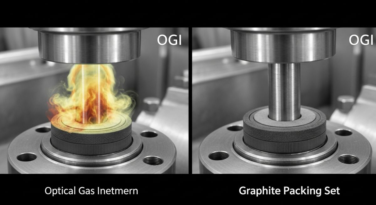
Visual Evidence: OGI Camera detection of a 450 ppm leak (Left) vs. Zero-Leakage with API 622 Graphite (Right).
The Problem
A petrochemical facility was facing heavy EPA fines due to “leaker” valves in high-pressure methane service. The existing PTFE braided packing was failing every 3 months due to thermal cycling, causing the stem seal to “relax” and leak.
Root Cause:
The PTFE packing was experiencing “Cold Flow” (creep) under the 1200 psi operating pressure, and the lack of Live-loading meant there was no way to compensate for the volume loss.
The Engineering Solution
The Epcland team implemented a Bespoke Sealing Upgrade:
- • Replaced PTFE with API 622 Certified Flexible Graphite rings.
- • Installed Belleville Spring Live-loading systems on all gland studs.
- • Polished stems to a 12 RMS finish.
Emissions Reduction
99.8% (< 5 ppm)
Maintenance ROI
2.5 Years Service Life
Compliance Status
EPA Level 1 Ready
Frequently Asked Questions (FAQ)
What is the difference between Valve Packing and a Gasket? ▼
How often should Valve Packing be replaced in a high-cycle environment? ▼
Why is Graphite Packing preferred over PTFE for steam applications? ▼
What are the signs of failing Valve Packing? ▼
Conclusion: Engineering Reliable Stem Seals
In the engineering landscape of 2026, Valve Packing is no longer a simple maintenance item—it is a critical technology for environmental compliance and operational efficiency. By selecting the correct material (Graphite vs PTFE), adhering to API 622 standards, and implementing modern Live-loading techniques, engineers can virtually eliminate stem seal leakage. Remember that a properly installed packing set not only prevents product loss but also protects your facility from costly regulatory fines and unplanned shutdowns.
📚 Recommended Resources: Valve Packing
Read these Guides
🎓 Advanced Training


Related posts:
![High-grade industrial Wing Nut Types and Applications for mechanical assemblies.]()
Wing Nut Types and Applications: The 2026 Engineering Guide
![Industrial Monorail Crane Systems installed in a modern manufacturing plant 2026.]()
Monorail Crane Systems: Design, Types & 2026 Standards Guide
![Lead engineer performing a Factory Acceptance Test FAT on an industrial skid system 2026]()
Factory Acceptance Test FAT: The 2026 Engineering Guide to Zero-Defect Delivery
![Professional engineering workspace showing a Basis of Design document layout for a 2026 project.]()
Basis of Design: How to Write a BOD for Engineering Projects in 2026
![Industrial Flare Knockout Drum Sizing and installation in a refinery relief system.]()
Flare Knockout Drum Sizing: Design & API 521 Standards (2026 Guide)
![Advanced Reboiler Control Systems in a modern petrochemical refinery 2026.]()
Reboiler Control Systems: Engineering Guide to Precision Control 2026


