Table of Contents
Stub-in vs Stub-on Piping Connections: Engineering Design Guide
Over my 20 years in the piping design trenches, I have seen countless field failures caused by poorly selected branch connections. When you are designing a piping system, choosing between a standard tee and a fabricated branch is your first major decision. But when you opt for a fabricated branch, the debate of stub-in vs stub-on immediately takes center stage. It is not just a matter of drafting convenience; it is a fundamental structural choice that dictates weld joint integrity, fluid dynamics, and long-term fatigue life under cyclic thermal loads.
In my experience, many junior engineers treat these two connections as interchangeable. This is a costly mistake. A stub-in connection requires the branch pipe to penetrate the header wall, whereas a stub-on connection sits flush on the header’s outer surface. Each has distinct welding profiles, fit-up tolerances, and reinforcement requirements under codes like ASME B31.3. Let us break down the engineering realities of these two configurations so you can make informed decisions on your next project.
Key Engineering Takeaways
- Structural Integrity: Stub-in connections offer superior resistance to bending and cyclic loads due to the mechanical interlock of the branch pipe penetrating the header.
- Flow Dynamics: Stub-on connections eliminate the risk of internal pipe protrusion, preventing localized turbulence and erosion-corrosion.
- Fabrication Effort: Stub-on connections require simpler hole cuts (matching branch ID) and are easier to align in the field compared to stub-ins.
- Code Compliance: Both configurations must undergo rigorous area replacement calculations per ASME B31.3 to determine if reinforcing pads are required.
Understanding Stub-in vs Stub-on Design Differences
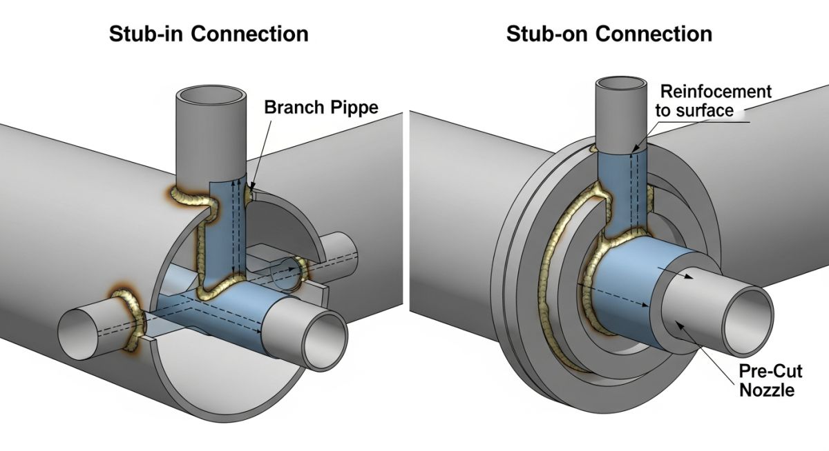
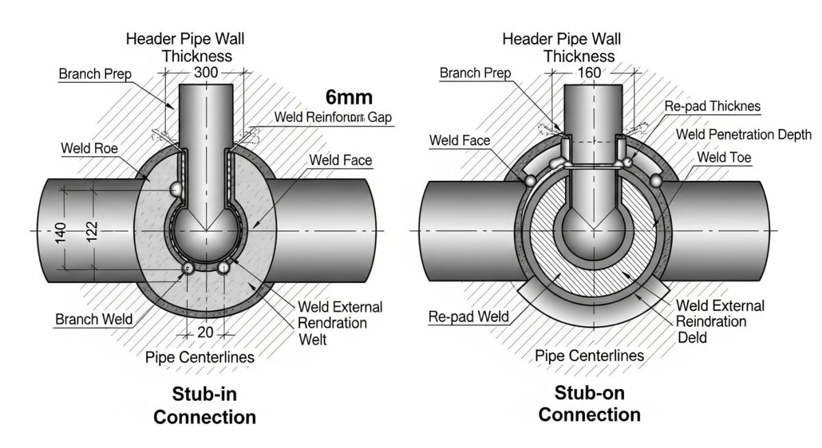
To truly understand the debate of stub-in vs stub-on, we must look at how the metal is cut and joined. In a stub-in configuration, the hole cut into the header pipe matches the outside diameter (OD) of the branch pipe. The branch pipe is inserted directly into this opening. This physical penetration provides a self-aligning mechanism during fit-up. However, it introduces a significant risk: if the fabricator does not carefully control the insertion depth, the branch pipe can protrude into the header run. This internal protrusion restricts flow, creates severe turbulence, and makes the line impossible to clean using standard pipeline pigs.
Conversely, a stub-on connection involves cutting a hole in the header that matches the inside diameter (ID) of the branch pipe. The branch pipe is then positioned directly on top of the header’s outer surface. Because the branch does not penetrate the header wall, there is zero risk of internal flow obstruction. This makes stub-on connections highly favored for utility lines, low-pressure systems, and piggable pipelines. The trade-off lies in weld strength. A stub-on relies entirely on an external fillet or groove weld, making it more susceptible to fatigue cracking under cyclic thermal expansion or mechanical vibration.
In my years of field auditing, I have seen stub-in connections where the branch pipe protruded up to 15mm into the header. This mistake not only caused a 12% pressure drop across the junction but also led to localized cavitation that eroded the header wall within 18 months of operation. Always specify a flush-fit tolerance on your fabrication drawings.
How to Calculate Reinforcement for Stub-in vs Stub-on
When you cut a hole in a header pipe, you weaken its ability to contain internal pressure. Under ASME B31.3 Section 304.3.3, we must perform an area replacement calculation. The fundamental principle is simple: the cross-sectional area of the metal removed by the hole must be compensated by excess metal available in the header wall, the branch wall, and the deposited weld metal.
Let us look at the governing equations. The required reinforcement area, A1, is calculated as:
Where:
• th is the pressure design thickness of the header.
• d1 is the effective length of the finished opening.
• beta is the angle between the branch and header axes (typically 90 degrees, making sin(beta) equal to 1).
The available area, A2, in the header wall is calculated as:
Where:
• d2 is the half-width of the reinforcement zone.
• Th is the nominal header thickness.
• c is the corrosion allowance.
If the sum of the available areas in the header (A2), branch (A3), and welds (A4) is less than the required area (A1), you must add a reinforcing pad (re-pad) to provide the missing area (A5). In my experience, stub-in connections often require slightly smaller re-pads than stub-ons because the branch pipe wall penetrating the header contributes to the available reinforcement area (A3) within the pressure boundary.
To help you quickly evaluate these configurations during the front-end engineering design (FEED) phase, I have compiled this comprehensive comparison matrix. It highlights the mechanical and operational trade-offs of each connection type.
| Design Parameter | Stub-in Connection | Stub-on Connection |
|---|---|---|
| Hole Cut Diameter | Matches branch outside diameter (OD) | Matches branch inside diameter (ID) |
| Weld Joint Type | Groove weld with fillet cover (penetrating) | Fillet weld or external groove weld (surface) |
| Flow Resistance | Moderate to high (risk of internal protrusion) | Low (smooth transition, flush ID) |
| Cyclic Load Resistance | Superior (better mechanical interlocking) | Lower (higher stress concentration at toe) |
| Ease of Fit-up | Difficult (requires precise alignment and depth control) | Easier (sits directly on header surface) |
| Re-pad Compatibility | Highly compatible (standard design) | Compatible (requires careful weld sizing) |
This matrix maps the core technical entities, structural parameters, and hyperlinked standard references required to execute fabricated branch connections in compliance with international codes.
| Entity / Parameter | Applicable Code | Engineering Definition | Design Impact |
|---|---|---|---|
| ASME B31.3 | ASME B31.3 | Process Piping Code governing design and fabrication | Mandates area replacement calculations and NDE rules |
| API 570 | API 570 | Piping Inspection Code for in-service systems | Governs localized corrosion monitoring at branch welds |
| Weld Joint Efficiency (Ej) | ASME B31.3 Table 302.4.3 | Numerical factor representing weld reliability | Directly reduces allowable stress if NDE is not performed |
| Stress Concentration (SCF) | ASME B31.3 Appendix D | Multiplier for localized stress at geometric transitions | Determines fatigue life under cyclic thermal expansion |
| Reinforcing Pad (Re-pad) | ASME B31.3 Para 328.5.4 | Donut-shaped plate welded around the branch neck | Restores structural strength lost by cutting the header |
Site Verification Checklist for Fabricated Branch Connections
In my experience, the transition from engineering drawings to field fabrication is where most errors occur. A single misaligned cut or an omitted vent hole can compromise the entire piping system. Use this checklist on-site to verify that your stub-in and stub-on connections are fabricated to the highest standards.
Field Inspection Checkpoints
-
✓
Hole Dimension Verification: Confirm that the header hole diameter matches the branch outside diameter (for stub-ins) or the branch inside diameter (for stub-ons) within a tolerance of +/- 1.5mm. -
✓
Penetration Depth Control: For stub-in connections, physically inspect the inside of the header to ensure the branch pipe is flush with the internal wall and does not protrude. -
✓
Weld Bevel Inspection: Verify that the branch pipe end has a clean 37.5-degree bevel and that the root gap is maintained between 1.6mm and 3.2mm before welding. -
✓
Tell-Tale Vent Hole: Ensure that all reinforcing pads (re-pads) are drilled with a 1/4-inch NPT vent hole. This hole must remain unplugged to prevent pressure build-up during welding and to allow future leak detection. -
✓
Pneumatic Pad Testing: Perform a low-pressure pneumatic test (typically 5 to 15 psi) on the reinforcing pad using soapy water to check for weld bubbles before final system hydrotesting. -
✓
NDE Compliance: Confirm that Dye Penetrant (PT) or Magnetic Particle (MT) testing has been performed on the root pass and final cover pass of the branch weld as specified by the piping class.
Field Case Study: Real-World Application
During a routine turnaround at a major refinery, inspectors discovered a crack propagating along the weld toe of a 4-inch Sch 80 bypass line connected to a 16-inch Sch 40 gas header. The original design utilized an unreinforced stub-on connection. Because the line was subjected to high-frequency acoustic vibration and thermal cycling from a nearby control valve, the high stress concentration at the stub-on weld toe led to rapid fatigue cracking. The system was dangerously close to a catastrophic hydrocarbon release.
I was brought in to lead the failure analysis and redesign. We quickly ruled out another stub-on connection due to its poor fatigue resistance. Instead, we engineered a reinforced stub-in connection. By inserting the branch pipe into the header, we achieved a mechanical interlock that significantly reduced the localized bending moment.
We specified a full-penetration groove weld with a reinforcing pad (re-pad) fabricated from the same material as the header. A 1/4-inch NPT tell-tale hole was drilled into the pad. To ensure maximum weld quality, we mandated 100% Ultrasonic Testing (UT) on the branch-to-header weld before installing the re-pad. This engineering intervention reduced the localized Stress Concentration Factor (SCF) by approximately 35%. The bypass line has now been operating under severe cyclic conditions for over six years without a single trace of micro-cracking.
My direct recommendation for any piping system operating under cyclic thermal or mechanical loads is to avoid unreinforced stub-on connections entirely. If a standard ASME B16.9 tee is not feasible due to space or lead-time constraints, a reinforced stub-in with a full-penetration weld is your safest, most reliable alternative.
Frequently Asked Engineering Questions
What is the primary difference between a stub-in and a stub-on connection?
When should I use a stub-in instead of a stub-on connection?
Does ASME B31.3 prefer stub-in or stub-on connections?
Why do reinforcing pads require a vent hole (tell-tale hole)?
Can stub-in connections be used in piggable pipelines?
How does the stress concentration factor (SCF) compare between stub-in and stub-on?
Complete Course on
Piping Engineering
Check Now
Key Features
- 125+ Hours Content
- 500+ Recorded Lectures
- 20+ Years Exp.
- Lifetime Access
Coverage
- Codes & Standards
- Layouts & Design
- Material Eng.
- Stress Analysis

📚 Recommended Resources: stub-in vs stub-on
Read these Guides


Related posts:
![An engineer performing an API 579 fitness for service assessment on an industrial pressure vessel.]()
How to Perform API 579 Fitness for Service Assessment
![3D CAD render of a bolted flange joint assembly showing a compressed gasket.]()
Understanding Gasket m and y Factors in Flange Design
![PASS/START-PROF 4.86 pipe stress analysis software interface displaying a 3D piping model.]()
PASS/START-PROF 4.86 Released: Discover the New Pipe Stress Analysis Capabilities
![ASME certification mark stamped on an industrial pressure vessel nameplate]()
What is ASME Certification? Procedure and Mark Explained
![Professional technician inserting a high-pressure hydro jetting nozzle into a sewer pipe cleanout.]()
What is Hydro Jetting and How Does It Work?
![A restriction orifice plate installed between pipe flanges in an industrial piping system.]()
What is a Restriction Orifice? Working, Types, and Sizing Guide