Ultimate Guide to Steam Piping Design: Engineering Considerations for 2026
Steam Piping Design is the critical engineering process of calculating, routing, and supporting pressurized systems to ensure the safe delivery of thermal energy in industrial environments.

Quick Definition: What is Steam Piping Design?
Steam Piping Design involves selecting materials, calculating pipe diameters based on velocity, and configuring supports to transport steam safely. Essential design elements include compliance with ASME B31.1 standards, implementing a 1:200 slope for condensate drainage, and integrating thermal expansion loops to manage high-temperature stresses within the 2026 regulatory framework.
Table of Contents
- Fundamental Principles of Steam Piping Design
- Essential Components within a Steam Piping Design
- Technical Standards: ASME B31.1 and API Requirements
- Critical Sizing Metrics for Steam Piping Design
- Managing Thermal Expansion and Condensate Drainage
- Maintenance and Safety in Steam Piping Design
- Steam Piping Design Performance Quiz
Steam Piping Design Performance Quiz
QUESTION 1 OF 5According to ASME B31.1, what is the standard recommended slope for a steam main to facilitate gravity condensate drainage?
Quiz Complete!
You have mastered the fundamentals of Steam Piping Design.
Complete Course on
Piping Engineering
Check Now
Key Features
- 125+ Hours Content
- 500+ Recorded Lectures
- 20+ Years Exp.
- Lifetime Access
Coverage
- Codes & Standards
- Layouts & Design
- Material Eng.
- Stress Analysis
Fundamental Principles of Steam Piping Design
The core objective of any Steam Piping Design is to transport steam from the generation source to the point of use with minimal heat loss and pressure drop. Unlike water systems, steam is a compressible gas that undergoes phase changes, making the management of condensate and thermal expansion critical. In 2026, modern engineering practices emphasize high-efficiency delivery systems that mitigate “water hammer” and maximize energy recovery.
Defining the Steam Piping Network
An industrial steam network is more than just a series of pipes; it is a dynamic energy distribution system. A robust Steam Piping Design must account for the specific volume changes that occur as steam loses pressure. Because steam occupies significantly more volume than the water it was generated from, pipe routing must accommodate high volumetric flow rates without exceeding erosive velocity limits.
Roles of Saturated vs. Superheated Steam in Steam Piping Design
Engineers must distinguish between saturated and superheated steam during the initial stages of Steam Piping Design. Saturated steam is typically used for process heating due to its high latent heat, but it requires diligent condensate management. Superheated steam, often found in 2026 power generation facilities, is used to drive turbines. It contains no moisture, reducing the risk of blade erosion, but it operates at much higher temperatures, necessitating specialized alloy materials.
Essential Components within a Steam Piping Design
Every component integrated into a Steam Piping Design must be rated for the maximum allowable working pressure (MAWP) and temperature of the system. Failure to match component ratings with boiler output is a primary cause of industrial accidents.

Boiler Header and Delivery Systems
The boiler header acts as the primary distribution hub. In a professional Steam Piping Design, the header must be sized to maintain low steam velocities, allowing any entrained moisture to drop out before the steam enters the main distribution lines. This “dry steam” is essential for protecting downstream control valves.
Industrial Valves and Control Instrumentation
Valves serve as the “gatekeepers” of the system. Common types used in Steam Piping Design include:
- Gate Valves: Used for isolation; they provide minimal pressure drop when fully open.
- Globe Valves: Preferred for throttling applications where precise flow control is required.
- Check Valves: Critical for preventing backflow into the boiler or across different pressure zones.
High-Pressure Fittings and Flanges
Fittings in Steam Piping Design must adhere to strict thickness requirements. For high-pressure steam, forged steel socket-weld or butt-weld fittings are standard. Flanges must be selected according to ASME B16.5, with Class 150, 300, or 600 being the most common depending on the operating envelope.
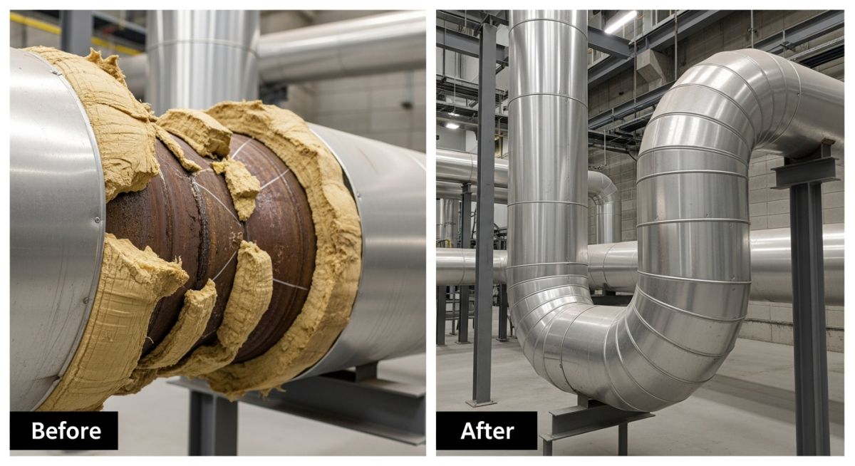
Advanced Thermal Insulation Materials
Insulation is no longer just about safety; in 2026, it is about sustainability. Modern Steam Piping Design utilizes calcium silicate or mineral wool with aluminum jacketing to reduce radiant heat loss. Effective insulation can reduce energy waste by up to 90 percent compared to uninsulated pipes.
Steam Traps and Condensate Removal in Steam Piping Design
The steam trap is arguably the most vital component. It must automatically discharge condensate while preventing the escape of live steam. Within a Steam Piping Design, traps are categorized as mechanical (float/inverted bucket), thermostatic, or thermodynamic (disc). Each has specific use cases based on the required discharge capacity and pressure.
Technical Standards: ASME B31.1 and API Requirements
Compliance with established codes is mandatory for legal and safety reasons. The primary standard for Steam Piping Design in power plants is ASME B31.1 (Power Piping). This code dictates the minimum wall thickness, material allowable stresses, and inspection requirements. For steam systems within refineries or chemical plants, ASME B31.3 (Process Piping) is often the governing standard. Furthermore, API 598 and API 600 standards guide the selection and testing of the valves used throughout the network.
Don’t miss this video related to Steam Piping Design

Summary: Master Piping Engineering with our complete 125+ hour Certification Course: ……
Critical Sizing Metrics for Steam Piping Design
Precision in Steam Piping Design sizing is the difference between a high-efficiency plant and one plagued by erosion and noise. Sizing is primarily governed by two constraints: allowable pressure drop and maximum steam velocity. In 2026, engineers utilize advanced computational fluid dynamics (CFD) to validate these metrics before installation.
Steam Pipe Sizing via Velocity and Pressure Drop
High steam velocity leads to pipe wall erosion, especially if moisture is present, while low velocity leads to oversized pipes and excessive heat loss. For saturated Steam Piping Design, the industry standard velocity range is 25 to 40 meters per second (m/s). For superheated steam, velocities can reach up to 60 or 80 m/s depending on the specific application.
Fundamental Velocity Equation:
V = (21.22 x W x v) / d2
Where:
V = Velocity in meters per second (m/s)
W = Mass flow rate in kilograms per hour (kg/h)
v = Specific volume of steam in cubic meters per kilogram (m3/kg)
d = Internal diameter of the pipe in millimeters (mm)
Material Selection (Carbon Steel vs. Alloy)
Material choice in Steam Piping Design is dictated by the ASME B31.1 operating temperature limits. While carbon steel is ubiquitous, its strength diminishes significantly above 425 degrees Celsius due to graphitization.
| Material Specification | Common Use Case | Max Temp (Approx) |
|---|---|---|
| ASTM A106 Grade B | Standard Carbon Steel for Saturated Steam | 425 Degrees C |
| ASTM A335 P11/P22 | Low Alloy Steel for Superheated Steam | 550 Degrees C |
| ASTM A335 P91 | High Alloy Steel for Power Generation | 600+ Degrees C |
| ASTM A312 TP304/316L | Stainless Steel for Clean/Corrosive Steam | Limit based on Pressure |
Calculated Slope for Condensate Flow
To prevent the accumulation of water, which causes destructive water hammer, Steam Piping Design must incorporate a downward slope in the direction of steam flow. A minimum slope of 1:200 (50mm for every 10 meters) is mandatory. If the pipe must slope upwards against the flow, the velocity must be significantly reduced, and the slope increased to at least 1:40 to ensure condensate can still drain effectively.
Branch Connections and Tee Reinforcements
When adding branches in Steam Piping Design, steam should always be taken from the top of the header. This ensures that the branch receives the driest possible steam, as condensate travels along the bottom of the pipe. Tee connections may require reinforcement pads if the branch diameter is more than half the header diameter, according to ASME stress calculations.
Managing Thermal Expansion and Condensate Drainage
Thermal expansion is an unavoidable reality in high-temperature steam systems. A 100-meter carbon steel pipe will expand approximately 250mm when heated from 20 degrees Celsius to 250 degrees Celsius. Without proper Steam Piping Design for flexibility, this expansion will buckle the pipe or tear out the anchors.
Expansion Loop Design for Thermal Stress
Expansion loops are the most reliable method for absorbing thermal movement. In a professional Steam Piping Design, these loops use the natural flexibility of the pipe material. U-bends and Z-bends are strategically placed between fixed anchors to ensure that the resultant stresses remain below the allowable limits defined in ASME B31.1.
Drip Leg Spacing and Sizing
Drip legs are vertical collection points located at regular intervals along the steam main. Current 2026 standards recommend placing a drip leg every 30 to 50 meters on straight runs and at the bottom of every vertical riser. For Steam Piping Design, the drip leg diameter should be the same as the main pipe diameter for pipes up to 100mm, and at least half the diameter for larger pipes to ensure high-velocity condensate is effectively captured.
Steam Piping Design Calculator
Estimate the steam velocity in your piping system based on 2026 engineering standards. Enter the mass flow, operating pressure, and internal pipe diameter to verify if your Steam Piping Design falls within the recommended 25-40 m/s range.
Calculated Steam Velocity
0.00 m/s
Note: This calculator uses an approximation of specific volume for saturated steam to assist in preliminary Steam Piping Design. For critical 2026 safety applications, always consult full ASME steam tables.
Engineering Case Study: Remediating Thermal Stress in Steam Piping Design
Project Data (2026)
- Facility Type: Regional Energy Recovery Plant
- Steam Condition: Saturated Steam at 15 bar g
- Flow Rate: 8,500 kg/h
- Line Length: 120 meters (Straight Run)
- Operating Temp: 201 degrees Celsius
Failure Analysis
During the 2026 commissioning phase, the system experienced severe lateral pipe movement at the mid-point. Post-incident inspection revealed that the primary anchor plates had begun to deform, and several sliding supports had jumped off their beams. The Steam Piping Design had failed to account for the cumulative thermal expansion of 285mm, causing the pipe to buckle under axial load.
The Engineering Fix
The remediation team performed a comprehensive stress analysis using CAESAR II software to revise the Steam Piping Design. The straight 120-meter run was split into three distinct 40-meter sections. A "U-shaped" expansion loop with a 4-meter offset was installed at the center of each section. Furthermore, the original rigid guides were replaced with low-friction PTFE-lined sliding supports to ensure smooth longitudinal movement without inducing lateral torque on the structural steel.
Lessons Learned
This case highlights two critical rules for modern Steam Piping Design:
- Anchor Capacity: Anchors must be designed to withstand the full "spring rate" force of the expansion loop, not just the static weight of the pipe.
- Guide Placement: The first guide must be placed within 4 pipe diameters of the expansion loop, and the second within 14 diameters, to prevent the pipe from bowing before the loop can absorb the growth.
- Cost of Failure: The retrofit cost exceeded 45,000 USD, whereas the correct initial design would have added less than 5,500 USD to the project budget.
"By 2026, automated stress modeling has become a prerequisite for Steam Piping Design. This project serves as a reminder that physical laws of thermal expansion cannot be ignored, even in highly optimized digital models."
Frequently Asked Questions: Steam Piping Design
Why is ASME B31.1 compliance mandatory for high-pressure steam distribution systems?
How do you calculate the required expansion loop size for thermal stress management?
What are the consequences of incorrect drip leg spacing on industrial steam system safety?
Which material selection provides the best corrosion resistance for clean steam applications?
Conclusion
Mastering Steam Piping Design is an essential skill for mechanical and piping engineers in 2026. By balancing complex variables such as steam velocity, thermal expansion, and condensate drainage, you can create systems that are not only safe but also exceptionally energy-efficient.
From adhering to ASME B31.1 standards to implementing precise material selection and advanced insulation, every detail contributes to the longevity of the plant. As industrial requirements continue to evolve, the fundamentals of robust Steam Piping Design remain the cornerstone of safe thermal energy distribution.
📚 Recommended Resources: Steam Piping Design
Read these Guides
🎓 Advanced Training


Related posts:
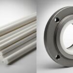
![Comparison of raw PTFE material and an industrial PTFE-lined steel pipe flange]()
Teflon vs PTFE: Major Differences in Industrial Piping Applications
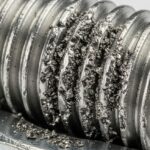
![Severe metal galling damage on a stainless steel threaded bolt and nut.]()
What is Metal Galling and How to Prevent It
![Certified welder performing structural welding repair on a heavy steel beam with sparks flying.]()
Mastering Industrial Welding Repair Procedures for Structural Integrity
![A fully assembled industrial pump skid system with stainless steel piping and control panels in a factory.]()
What is an Industrial Pump Skid and Its Key Advantages?
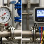
![Side-by-side comparison of an industrial flow meter and a digital flow transmitter installed on a pipeline.]()
Flow Transmitter vs Flow Meter: Key Differences Explained
![Wireless vibration sensor mounted on an industrial electric motor for condition monitoring.]()
What is Vibration Monitoring and Why is it Important?