Rotating Equipment Piping Alignment: The 2026 Procedure for Process Piping Connections
Executing a precise Rotating Equipment Piping Alignment is the single most critical step in the commissioning of high-speed pumps, compressors, and turbines. Failure to eliminate “Pipe Strain” can lead to immediate mechanical seal failure, bearing overheating, and catastrophic vibration. In 2026, the industry adheres to strict API 686 protocols to ensure that the process piping does not exert external forces on the machine casing, maintaining the equipment’s internal clearances and long-term reliability.
What is Pipe Strain in Rotating Equipment?
Pipe strain occurs when poorly aligned piping is forced into connection with a machine’s flanges. During Rotating Equipment Piping Alignment, engineers must ensure the piping is self-supporting. If the machine’s shaft moves more than 0.05 mm (0.002 inches) when flanges are tightened, excessive pipe strain is present.
Table of Contents
- Preservation and Preparation for Rotating Equipment Piping Alignment
- Structural Readiness: Piping Completeness and Support Systems
- Flange Fitting Tolerances for Rotating Equipment Piping Alignment
- Execution: Preliminary Tests and Connection References
- Pre-Tightening Operations and Intermediate Alignment Check
- Final Verification: Final Alignment Check and Fixing
Technical Competency Quiz: Piping Alignment
1. What is the maximum allowable shaft movement during flange bolt-up according to API 686?
Complete Course on
Piping Engineering
Check Now
Key Features
- 125+ Hours Content
- 500+ Recorded Lectures
- 20+ Years Exp.
- Lifetime Access
Coverage
- Codes & Standards
- Layouts & Design
- Material Eng.
- Stress Analysis
Preservation and Preparation for Rotating Equipment Piping Alignment
Before the physical mating of flanges begins, a rigorous preservation phase must be concluded. In the context of Rotating Equipment Piping Alignment, preparation starts with ensuring that the machine’s internal components are protected from environmental debris and corrosion. This involves verifying that all desiccant bags are removed and that the shaft can be rotated freely by hand without any abnormal resistance or noise.
API 686 Recommended Practice for Initial Setup
Adhering to the API 686 Recommended Practice ensures that the machine is in a “stress-free” state before piping is introduced. This includes verifying the levelness of the baseplate and the initial alignment of the driver (motor or turbine) to the driven equipment. Without this baseline, any subsequent piping adjustments will be inherently flawed, potentially leading to cumulative Shaft Misalignment Tolerances that exceed engineering limits.
Critical Checklist for Preparation:
- Verify that the equipment foundation has reached 100 percent grout strength.
- Ensure that all shipping brackets and “bright-work” protective coatings have been removed.
- Confirm that the suction and discharge nozzles are covered with metal blinds until the moment of alignment.
Machine Protection and Electrical Insulation Requirements
A frequently overlooked step in Rotating Equipment Piping Alignment is the verification of bearing insulation. For many large motors and compressors, the non-drive end bearing is electrically insulated to prevent stray currents from causing EDM (Electrical Discharge Machining) pitting on the bearing rollers. Engineers must use a megohmmeter to verify that the insulation remains intact after the machine is leveled but before the piping provides a secondary grounding path.
Structural Readiness: Piping Completeness and Support Systems
For a successful Rotating Equipment Piping Alignment, the process piping must be structurally complete up to the second or third permanent support from the machine nozzle. This ensures that the piping system’s weight is fully carried by its own supports rather than being transferred to the sensitive machine casing.
Role of Temporary and Permanent Supports in Alignment
During the construction phase, temporary supports are often used to position large bore pipes. However, before starting the Pipe Strain Analysis, these must be replaced by permanent, adjusted supports. Spring hangers must be locked in their “cold” position, and rigid supports must be shimmed to ensure the pipe flange floats naturally in front of the machine nozzle without external force.
| Support Type | Requirement during Alignment | Impact on Machine |
|---|---|---|
| Rigid Support | Fully shimmed and bolted | Prevents vertical dead-load transfer |
| Spring Hanger | Pinned/Locked in cold position | Maintains design elevation during fit-up |
| Temporary Cleats | Removed prior to final bolt-up | Eliminates artificial system stiffness |
Flange Fitting Tolerances for Rotating Equipment Piping Alignment
The success of Rotating Equipment Piping Alignment is measured by the “natural” fit of the piping flanges to the equipment nozzles. In 2026, field engineers utilize the API 686 Recommended Practice to define the maximum allowable deviations. If a flange must be pulled, pushed, or pried into place, the resulting pipe strain will distort the machine casing, leading to internal rubbing and premature failure of mechanical seals.
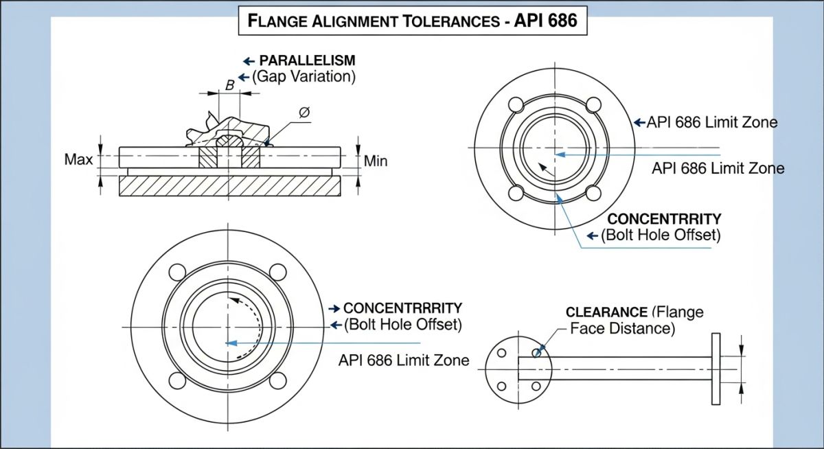
Measuring Flange Face Parallelism, Clearance, and Concentricity
Before any bolts are inserted, three critical geometric checks must be performed on the flange interface. These measurements ensure that the Flange Face Parallelism is within acceptable limits, preventing an uneven load on the gasket which could cause leakage or localized stress on the machine nozzle.
| Parameter | API 686 Standard Limit | Measurement Tool |
|---|---|---|
| Parallelism | 0.25 mm (0.010 in) maximum | Feeler Gauges / Calipers |
| Concentricity | Bolt holes align within 3.0 mm (1/8 in) | Standard Flange Bolts |
| Clearance (Gap) | Gasket thickness plus 1.5 mm (1/16 in) | Inside Micrometers |
Mathematical verification for parallelism involves measuring the gap at four points (12, 3, 6, and 9 o’clock positions). The difference between the maximum and minimum readings must be less than 0.25 mm. For high-pressure services, this tolerance is often reduced to 0.10 mm to ensure a perfectly uniform gasket seat.
Execution: Preliminary Tests and Connection References
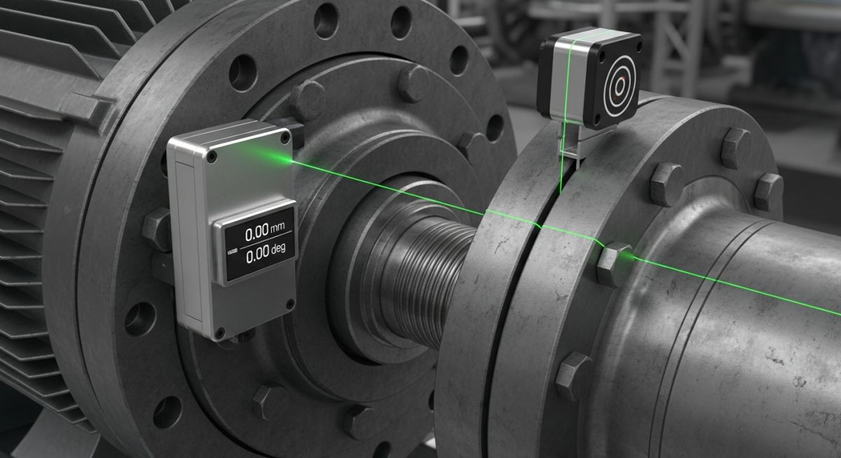
Once the physical tolerances are met, the Rotating Equipment Piping Alignment procedure transitions into active monitoring. This phase requires the installation of Dial Indicator sets or laser alignment sensors on the coupling of the machine. The goal is to detect any Shaft Misalignment Tolerances being exceeded as the weight of the piping system is introduced to the machine.
The Elastic Support Check (Soft Foot Analysis)
The “Elastic Support Check,” commonly referred to as a Soft Foot Check, is mandatory before the final piping connection. Each anchor bolt of the machine is loosened one by one while monitoring the Dial Indicator Method on the shaft. If loosening a bolt causes the shaft to move more than 0.05 mm (0.002 inches), the foot is “soft” and must be shimmed. A soft foot makes it impossible to achieve a stable Rotating Equipment Piping Alignment because the casing will twist every time the foundation bolts are torqued.
Pre-Tightening Operations and Intermediate Alignment Check
After verifying the soft foot, the flanges are brought together for “Pre-Tightening.” During this stage of Rotating Equipment Piping Alignment, bolts are inserted by hand. If a hammer is required to drive a bolt through the flange holes, the Concentricity is insufficient, and the piping supports must be readjusted.
Intermediate Verification and Piping Restoration
An intermediate check is performed when the bolts are at 25 percent of their final torque. The Pipe Strain Analysis involves watching the shaft position indicators. If the shaft moves significantly during this initial take-up, the bolts must be loosened and the piping alignment corrected. This iterative process prevents the accumulation of stresses that would otherwise lead to “Cold Spring” errors, where the pipe acts as a giant spring trying to pull the pump off its baseplate.
Rotating Equipment Piping Alignment Calculator
This tool validates your field measurements against API 686 standards for flange parallelism and allowable pipe strain. Input your readings to determine if the connection is ready for final bolt-up.
Don’t miss this video related to Equipment Piping Alignment

Summary: Master Piping Engineering with our complete 125+ hour Certification Course: ……
Case Study: Solving Vibration Issues via Rotating Equipment Piping Alignment
Project Data
- Equipment: 4500 HP Multi-Stage Centrifugal Compressor
- Service: Wet Gas Compression
- Pipe Size: 24-inch Suction / 18-inch Discharge
- Observed Issue: High vibration (8.5 mm/s) during initial run-up
- Potential Revenue Loss: 85,000 USD per day
Failure Analysis
Post-commissioning vibration analysis indicated a 1X frequency peak, suggesting misalignment. However, laser alignment of the shafts in the “un-piped” state was perfect. The engineering team performed a pipe strain test by monitoring the coupling while loosening the suction flange. The dial indicator jumped 0.22 mm (0.009 inches), indicating that the Rotating Equipment Piping Alignment was compromised by a massive external load from the suction line.
The Engineering Fix
The team discovered that a permanent rigid support located 4 meters from the compressor nozzle was 6 mm too high, effectively prying the compressor casing upward. The support was re-shimmed, and the pipe was re-fabricated to meet API 686 Recommended Practice for flange parallelism. During the final bolt-up, shaft movement was limited to only 0.02 mm.
Lessons Learned
- Laser Accuracy is Secondary to Pipe Strain: A machine can be perfectly aligned to its motor, but pipe strain will twist the casing, ruining the internal clearances regardless of shaft alignment.
- Support Verification is Mandatory: Always check the elevation and load-setting of every support between the machine and the first anchor point.
- Dial Indicator Monitoring: Never perform a final flange bolt-up without a dial indicator on the machine coupling to verify Rotating Equipment Piping Alignment in real-time.
Final Verification: Final Alignment Check and Fixing
The culmination of the Rotating Equipment Piping Alignment procedure is the “Final Fixing.” This occurs only after the suction and discharge piping have been fully bolted and torqued. A final check of the shaft alignment is performed using laser or dial indicator methods to ensure the “piped” state matches the “un-piped” state within 0.05 mm.
API 686 Compliance and Shaft Movement Monitoring
Once the final check is complete, the machine is “fixed” by installing dowel pins in the feet of the driven equipment (if required by the manufacturer). These pins ensure the machine cannot shift over time due to thermal cycling. However, in modern 2026 practice, many high-speed machines are left “un-pinned” to allow for thermal growth, provided the Rotating Equipment Piping Alignment has accounted for these movements during the cold-setting phase.
Frequently Asked Questions: Rotating Equipment Piping Alignment
What is the primary indicator of excessive pipe strain during alignment?
The primary indicator of excessive pipe strain is any vertical or horizontal movement of the equipment shaft exceeding 0.05 mm (0.002 inches) during the flange bolt-up process. During Rotating Equipment Piping Alignment, this is measured using dial indicators or laser sensors mounted on the coupling. Any movement beyond this limit suggests the piping is prying the machine casing out of its designed geometric center.
How do API 686 Recommended Practice tolerances differ from standard piping?
Standard piping tolerances focus on fit-up for welding, whereas API 686 Recommended Practice focuses on preventing stress transfer to rotating machinery. API 686 requires Flange Face Parallelism to be within 0.25 mm and bolt hole Concentricity to allow hand-insertion of bolts. Standard piping may allow several millimeters of deviation, but such gaps are unacceptable when connecting to sensitive machines like high-speed compressors.
When should the final alignment check be performed?
The final alignment check must be performed twice. First, after all Rotating Equipment Piping Alignment activities are finished and the flanges are fully torqued in the “cold” state. Second, a “Hot Alignment” check is often required after the machine has reached normal operating temperature to account for thermal growth of the piping and equipment casing.
Can pipe strain cause mechanical seal failure?
Absolutely. Pipe strain is one of the leading causes of premature mechanical seal failure. When Rotating Equipment Piping Alignment is poor, the casing distorts, which shifts the seal chamber relative to the shaft. This causes the seal faces to run eccentrically or with an uneven load, leading to rapid wear, heat generation, and eventual leakage of process fluids.
