Comprehensive Guide to Reciprocating Compressor Sizing
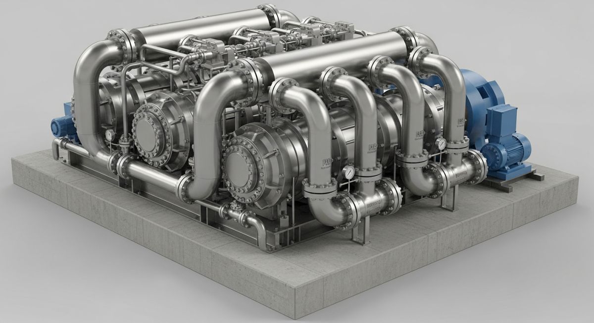
Reciprocating Compressor Sizing is a critical engineering process governed by API 618 standards to ensure the reliable delivery of process gases in refineries and chemical plants. In 2026, precision in calculating cylinder displacement and rod loads remains the cornerstone of mechanical integrity and operational efficiency.
What is Reciprocating Compressor Sizing?
Reciprocating Compressor Sizing is the multi-step engineering procedure used to determine the required cylinder bore, stroke, and stage count to meet specific mass flow rates. It involves calculating compression ratios, volumetric efficiency, and brake horsepower (BHP) while ensuring gas rod loads stay within frame limits per API 618 or API 11P.
Technical Knowledge Check: Compressor Sizing
Question 1/5
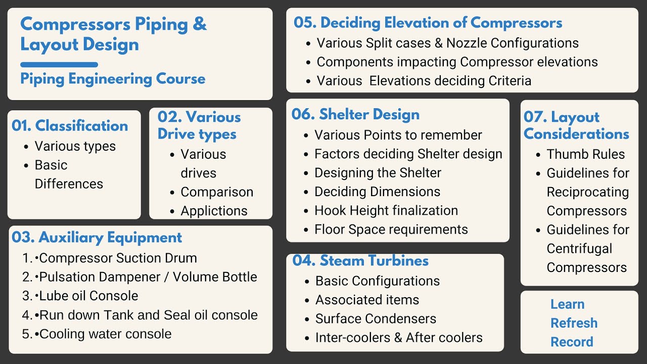
Complete Course on
Piping Engineering
Check Now
Key Features
- 125+ Hours Content
- 500+ Recorded Lectures
- 20+ Years Exp.
- Lifetime Access
Coverage
- Codes & Standards
- Layouts & Design
- Material Eng.
- Stress Analysis
API 618 and ISO Standards for Reciprocating Compressor Sizing
When performing Reciprocating Compressor Sizing, adherence to international standards ensures both safety and performance. The primary benchmark for heavy-duty process industry applications is API 618 (Reciprocating Compressors for Petroleum, Chemical, and Gas Industry Services). This standard defines strict requirements for speed, vibration, and mechanical design. For high-speed applications, engineers refer to API 11P or ISO 13631.

Selecting the Proper Reciprocating Compressor Sizing Methodology
The sizing process is iterative. It begins with the process conditions (mass flow, gas composition, suction pressure, and temperature) and concludes with the selection of a mechanical frame and cylinder bores that can withstand the resulting Gas Rod Loads.
Fundamental Principles of Reciprocating Compressor Sizing
Step 1: Calculate the Compression Ratio (CR)
The compression ratio is the fundamental driver of heat and efficiency. It is calculated by dividing the absolute discharge pressure by the absolute suction pressure. In Reciprocating Compressor Sizing, we aim to keep the CR per stage below 4.0 to manage discharge temperatures.
Step 2: Determine Stages for Reciprocating Compressor Sizing
Multiple stages are required when the total compression ratio exceeds the safe limit of a single cylinder. Staging reduces the discharge temperature and minimizes the required Brake Horsepower (BHP). The goal is to equalize the compression ratio across all stages to balance the load.
Step 3: Calculate Estimated Brake Horsepower (BHP)
Power estimation is vital for driver selection (motor or engine). The BHP is derived from the adiabatic or polytropic head required to move the gas. During Reciprocating Compressor Sizing, a mechanical efficiency of 95 percent is typically applied to the gas power to account for frame losses.
Step 4: Calculate Estimated Discharge Pressure (Psia)
The discharge pressure at each stage must account for pressure drops through intercoolers and pulsation dampeners. Accurate pressure modeling ensures that the final stage meets the process requirement.
Step 5: Calculate Discharge Temperature and Heat of Compression
Excessive temperature can destroy valve plates and piston rings. The discharge temperature is a function of the suction temperature, CR, and the isentropic exponent (k) of the gas. Per API 618, the limit is usually 135 degrees C for most refinery services.
Suction Volumetric Efficiency in Reciprocating Compressor Sizing
Volumetric Efficiency (VE) is perhaps the most critical variable in Reciprocating Compressor Sizing. It represents the ratio of the actual volume of gas taken into the cylinder to the displacement of the piston. Factors such as clearance volume, valve losses, and gas slippage play a significant role.
| Parameter | Standard API 618 | High Speed (API 11P) |
|---|---|---|
| Avg. Piston Speed | 4.0 to 4.5 m/s | Up to 5.5 m/s |
| Valve Velocity | Low (Efficiency focus) | High (Compact focus) |
| Discharge Temp Limit | 135 degrees C | 150 to 165 degrees C |
Step 7: Calculate Required Piston Displacement and Cylinder Bore
Once the VE is determined, the Reciprocating Compressor Sizing requires calculating the required Piston Displacement (PD). This is the total volume swept by the piston per unit of time.
PD = (Actual Flow Rate) / (Volumetric Efficiency)
Note: Actual flow must be converted to suction conditions (P1, T1, Z1).
Evaluate Gas Rod Loads and Frame Ratings
A critical safety check in Reciprocating Compressor Sizing is the gas rod load calculation. This is the force exerted on the piston rod due to the differential pressure across the piston.
Simplified Rod Load Logic:
- Tension Load: (Pdischarge x Areapiston rod side) – (Psuction x Areapiston head side)
- Compression Load: (Pdischarge x Areapiston head side) – (Psuction x Areapiston rod side)
Both values must be lower than the OEM frame rating to prevent catastrophic failure.
Step 8 & 9: Valve Velocity and OEM Data Integration
In 2026, Reciprocating Compressor Sizing software integrates OEM-specific valve dynamics. High valve velocity leads to increased “Stagewise” pressure drops, reducing the overall system efficiency. Proper sizing ensures the gas velocity through the valve lift area remains within conservative limits (typically 2,500 to 3,500 ft/min).
Don’t miss this video related to Reciprocating Compressor Sizing
Summary: Master Piping Engineering with our complete 125+ hour Certification Course: ……
Reciprocating Compressor Sizing Calculator
Estimate the Compression Ratio (CR) and theoretical Discharge Temperature (T2) for your 2026 preliminary sizing study.
Case Study: Reciprocating Compressor Sizing for Hydrogen Refinery Service
Project Data
A major refinery required Reciprocating Compressor Sizing for a Make-Up Hydrogen service with a suction pressure of 250 Psia and a target discharge of 1,200 Psia. The gas contained 98 percent Hydrogen (H2).
Failure Analysis (Initial Design)
The initial single-stage proposal resulted in a compression ratio of 4.8. This led to calculated discharge temperatures exceeding 160 degrees C, far above the API 618 limit of 135 degrees C. Furthermore, the Gas Rod Load exceeded the frame’s structural limit by 15 percent.

Engineering Fix & Final Sizing
The sizing was revised to a 2-stage configuration with intercooling.
- Stage 1: CR of 2.19 (250 to 548 Psia)
- Stage 2: CR of 2.19 (548 to 1200 Psia)
- Result: Discharge temperature dropped to 118 degrees C per stage.
- Integrity: Rod loads were reduced to 70 percent of frame capacity, ensuring a 20-year fatigue life.
Lessons Learned: High compression ratios in low-molecular-weight gases (like Hydrogen) drastically increase heat. Multi-stage Reciprocating Compressor Sizing is non-negotiable for high-pressure ratios to maintain mechanical integrity.
Common Questions on Reciprocating Compressor Sizing
How does Gas Molecular Weight affect Reciprocating Compressor Sizing? ▼
Why is API 618 critical for Reciprocating Compressor Sizing in refineries? ▼
What is the impact of Clearance Volume on Piston Displacement? ▼
How are Rod Load Limits calculated in modern sizing software? ▼
📚 Recommended Resources: Compressor
Read these Guides
🎓 Advanced Training


Related posts:
![High-grade industrial Wing Nut Types and Applications for mechanical assemblies.]()
Wing Nut Types and Applications: The 2026 Engineering Guide
![Industrial Monorail Crane Systems installed in a modern manufacturing plant 2026.]()
Monorail Crane Systems: Design, Types & 2026 Standards Guide
![Lead engineer performing a Factory Acceptance Test FAT on an industrial skid system 2026]()
Factory Acceptance Test FAT: The 2026 Engineering Guide to Zero-Defect Delivery
![Professional engineering workspace showing a Basis of Design document layout for a 2026 project.]()
Basis of Design: How to Write a BOD for Engineering Projects in 2026
![Industrial Flare Knockout Drum Sizing and installation in a refinery relief system.]()
Flare Knockout Drum Sizing: Design & API 521 Standards (2026 Guide)
![Advanced Reboiler Control Systems in a modern petrochemical refinery 2026.]()
Reboiler Control Systems: Engineering Guide to Precision Control 2026


