Comprehensive Guide to Piping Manifold Design: Applications, Types, and Standards
In modern process engineering, Piping Manifold Design serves as the central nervous system for fluid distribution, enabling the efficient convergence or divergence of multiple flow streams within a single header. This guide explores the critical parameters of 2026 mechanical standards to ensure system integrity and hydraulic balance.
At a Glance: What is a Piping Manifold?
A piping manifold is a specialized pipe fitting or fabricated assembly that connects a single larger header to multiple smaller branch lines. Used for fluid distribution or collection, effective Piping Manifold Design optimizes flow velocity and pressure distribution while minimizing space and material costs in complex industrial systems.
Table of Contents
- 1. Primary Purpose of a Piping Manifold
- 2. Key Applications of Piping Manifold Design
- 3. Fundamental Principles of Design
- 4. Common Types of Piping Manifolds
- 5. Specialized Pipeline Manifolds
- 6. Header vs. Manifold Differences
- 7. Critical Factors for Selection
- 8. Design vs. Modular Process Skids
- 9. Engineering FAQ
Piping Manifold Design Technical Quiz
Question 1 of 5
Complete Course on
Piping Engineering
Check Now
Key Features
- 125+ Hours Content
- 500+ Recorded Lectures
- 20+ Years Exp.
- Lifetime Access
Coverage
- Codes & Standards
- Layouts & Design
- Material Eng.
- Stress Analysis
What is the Primary Purpose of a Piping Manifold?
The fundamental objective of a Piping Manifold Design is to streamline fluid distribution or collection within a process plant. By utilizing a single header pipe to manage multiple branch connections, engineers can centralize control, reduce the physical footprint of the piping network, and minimize the number of individual pipe runs from a source to multiple destinations. In 2026, efficiency in material usage and pressure management remains the driving force behind sophisticated manifold integration.
Key Applications of Piping Manifold Design in Industry
Modern Piping Manifold Design is utilized across various sectors where precise flow management is non-negotiable. Key applications include:
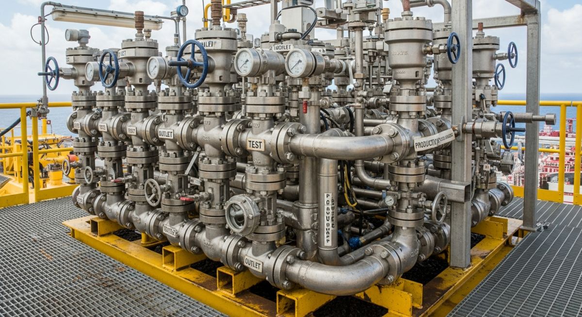
- Oil and Gas Production: Gathering lines from multiple wells into a single test or production separator.
- Chemical Processing: Distributing reagents from a storage tank to various batch reactors.
- Power Generation: Steam distribution headers that supply high-pressure steam to multiple turbine stages.
- HVAC Systems: Chilled water manifolds used for climate control in large-scale commercial complexes.
Fundamental Principles of Piping Manifold Design
Engineering a reliable manifold requires a deep understanding of fluid mechanics and mechanical integrity. The design must account for the total volumetric flow rate and the cumulative pressure drop across all active branches.
Material Selection and ASME B31.3 Compliance
To ensure safety and longevity, Piping Manifold Design must adhere to ASME B31.3 compliance for process piping. This involves selecting materials based on the fluid’s corrosivity, temperature, and design pressure. Common materials include Carbon Steel (ASTM A106), Stainless Steel (ASTM A312), and specialized alloys for high-temperature services. Wall thickness calculations must include a corrosion allowance to meet the 20-year service life standards expected in 2026.
Pressure Drop and Flow Velocity Optimization
Achieving flow velocity optimization is critical to prevent erosion and noise. In a distribution manifold, the header diameter is typically sized so that the flow velocity remains within 1.5 to 3.0 meters per second for liquids. Designers use hydraulic modeling to ensure that the pressure at the last branch is sufficient to meet process requirements, preventing “starvation” of downstream equipment.
Common Types of Piping Manifolds and Their Functions
When evaluating Piping Manifold Design, several configurations are categorized based on their flow direction and mechanical structure:
| Manifold Type | Flow Direction | Typical Use Case |
|---|---|---|
| Distribution Manifold | One Inlet to Multiple Outlets | Fuel supply to multiple burners |
| Collection Manifold | Multiple Inlets to One Outlet | Gathering lines from oil wells |
| Mixing Manifold | Multiple Inlets to Mixed Outlet | Blending different chemical streams |
Specialized Pipeline Manifolds for Midstream Operations
In midstream oil and gas, Piping Manifold Design transitions into heavy-duty specialized pipeline manifolds. These systems are engineered to handle massive volumes of crude oil or natural gas, often incorporating pig launchers and receivers. Design integrity follows ASME B31.4 or B31.8 standards, focusing on high-pressure ratings and environmental containment. In 2026, these manifolds are increasingly equipped with automated ESD (Emergency Shut Down) valves to enhance safety.
Piping Manifold Design: Header vs. Manifold Differences
While often used interchangeably, there is a technical distinction in Piping Manifold Design. A Header is a single pipe that acts as a common connection point for several smaller pipes. A Manifold is the entire assembly, including the header, branch connections, valves, and instrumentation. Essentially, the header is the “spine,” while the manifold is the “complete nervous system.”
Critical Factors for Selecting the Right Piping Manifold Design
| Design Factor | Engineering Consideration |
|---|---|
| Branch Reinforcement | Required if the opening area significantly reduces header strength per ASME B31.3. |
| Flow Imbalance | Mitigated by using a larger header diameter to equalize pressure across branches. |
| Thermal Expansion | Calculated to prevent stress at branch-to-header weld joints during temperature swings. |
Comparison: Piping Manifold Design vs. Modular Process Skids
Choosing between a standalone Piping Manifold Design and modular process skids depends on project complexity. A manifold is strictly for flow distribution, whereas a skid integrates the manifold with pumps, heat exchangers, and PLC control systems into a transportable steel frame. In 2026, the industry favors skids for offshore and remote locations due to reduced on-site labor and pre-tested performance.
Engineering Math: Header Thickness Calculation
Per ASME B31.3, the minimum required wall thickness (t) for a manifold header is calculated as:
t = (P * D) / (2 * (S * E + P * Y))
- P: Internal design gage pressure (Units: PSI or Bar)
- D: Outside diameter of the header pipe (Units: mm or inches)
- S: Stress value for material from allowable stress tables
- E: Quality factor (typically 1.0 for seamless pipe)
- Y: Coefficient based on material and temperature
Note: Final design thickness must include a 12.5% mill tolerance and a specific corrosion allowance for 2026 safety standards.
Piping Manifold Design Header Velocity Calculator
Use this 2026 engineering tool to estimate the fluid velocity within your manifold header. Maintaining optimal velocity (typically 1.5 to 3.0 m/s for liquids) is critical for Piping Manifold Design to prevent erosion and excessive pressure drop.
Calculated Header Velocity
0.00 m/s
Don't miss this video related to Piping Manifold Design

Summary: Welcome to our comprehensive 30-day course on ASME B31.3 - the code that governs process piping! 🛢️ In this single video, ......
Case Study: Optimizing Piping Manifold Design for Offshore Production
Project Data: In 2026, a major operator in the North Sea faced significant vibration issues in a 12-slot production manifold handling high-pressure crude. The original Piping Manifold Design utilized a standard 10-inch header that resulted in acoustic-induced vibration (AIV).
Failure Analysis: Engineering audits revealed that the flow velocity exceeded 4.5 meters per second during peak production, causing turbulent eddies at the branch-to-header junctions. This stress eventually led to hairline cracks in the Heat Affected Zone (HAZ) of the welds.
Engineering Fix & Lessons Learned
- Modification: The manifold was retrofitted with a 14-inch header to reduce velocity and integrated with Sweepolets for smoother flow transition.
- Standardization: Implementation of ASME B31.3 Chapter IX (High Pressure) welding protocols for all manifold branch connections.
- Outcome: Vibration levels dropped by 65 percent, extending the predicted fatigue life of the manifold by 15 years.
Engineering FAQ: Mastering Piping Manifold Design
How does fluid distribution systems balance influence header sizing? +
What are the manifold header thickness calculation requirements for 2026? +
Are modular process skids always better than field-fabricated manifolds? +
What role does branch connection reinforcement play in high-pressure manifolds? +
Conclusion: The Future of Piping Manifold Design
As we move through 2026, Piping Manifold Design continues to evolve toward higher levels of integration and digital monitoring. Whether you are designing a simple distribution header for a water treatment plant or a complex production manifold for an offshore rig, the principles of hydraulic balance, ASME compliance, and material integrity remain the pillars of engineering success.
By prioritizing flow velocity optimization and rigorous thickness calculations, engineers can ensure that their manifold systems operate safely and efficiently for decades to come.
📚 Recommended Resources: Piping Manifold Design
Read these Guides


Related posts:
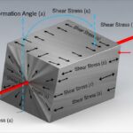
![3D engineering diagram illustrating shear modulus deformation on a solid block with force vectors.]()
Understanding Shear Modulus and Modulus of Rigidity in Piping Design
![3D render of a protective chromium oxide film forming on a stainless steel surface.]()
How Does Stainless Steel Oxide Film Formation Prevent Corrosion?
![Side-by-side comparison of industrial metal casting and metal forging processes.]()
Casting vs Forging: Key Differences for Industrial Piping Systems
![Various types of industrial pumps displayed in a modern engineering facility.]()
Guide to Types of Pumps and Their Working Principles
![3D digital GIS map overlay showing petroleum pipeline routes across a terrain]()
Why GIS in Petroleum and Pipeline Industry is Absolutely Critical
![CAESAR II Version 14 pipe stress analysis software interface displaying a 3D piping model.]()
What Is New in CAESAR II Version 14 Pipe Stress Analysis