What is Pipeline Girth Welding? The Complete Engineering Guide
Imagine you are standing on a remote right-of-way in the dead of winter. Your mechanized welding spread is hitting 80 joints a day, but the Automated Ultrasonic Testing (AUT) cabin just reported a string of “stacked” defects in the last five joints. If you don’t identify the root cause of this Pipeline Girth Welding failure within the hour, the project burns 50,000 USD in downtime. This is where engineering precision meets the harsh reality of the field.
This guide provides the technical depth required to manage, execute, and inspect high-integrity circumferential welds that define the lifespan of midstream assets.
Key Takeaways
- Standard Compliance: Understanding the divergence between API 1104 (Standard) and API 1104 (Appendix A) for girth weld acceptance.
- Process Evolution: Why mechanized GMAW has replaced manual SMAW for 36-inch plus transmission lines.
- Critical Integrity: The role of pre-heat and interpass temperature control in preventing Hydrogen Induced Cracking (HIC).
What is Pipeline Girth Welding?
Pipeline Girth Welding is the process of joining two individual pipe segments together using a circumferential butt weld. It is the primary method for constructing cross-country pipelines, requiring specialized multi-pass sequences (Root, Hot, Fill, and Cap) to ensure full penetration and structural integrity under high-pressure operating conditions.
Founder’s Insight
“In my 20 years of pipeline oversight, I’ve seen that a girth weld is only as good as its root pass. Whether you are using cellulosic electrodes or advanced mechanized systems, the alignment and internal clamp pressure dictate the final fatigue life of the joint. Never compromise on the fit-up.”
— Atul Singla
Table of Contents
- 1. What is Pipeline Girth Welding? (Definition & Scope)
- 2. Essential Pipeline Girth Welding Passes: From Root to Cap
- 3. Advanced Pipeline Girth Welding Methods (Manual vs. Mechanized)
- 4. Engineering Selection Criteria for Pipeline Girth Welding
- 5. Critical Procedures for Pipeline Girth Welding Tie-ins
- 6. Quality Control and API 1104 Standards
- 7. Expert Video Courses in Pipeline Girth Welding
- 8. Community Insights on Pipeline Girth Welding
Complete Course on
Piping Engineering
Check Now
Key Features
- 125+ Hours Content
- 500+ Recorded Lectures
- 20+ Years Exp.
- Lifetime Access
Coverage
- Codes & Standards
- Layouts & Design
- Material Eng.
- Stress Analysis
Loading Question…
What is Pipeline Girth Welding? (Definition & Scope)
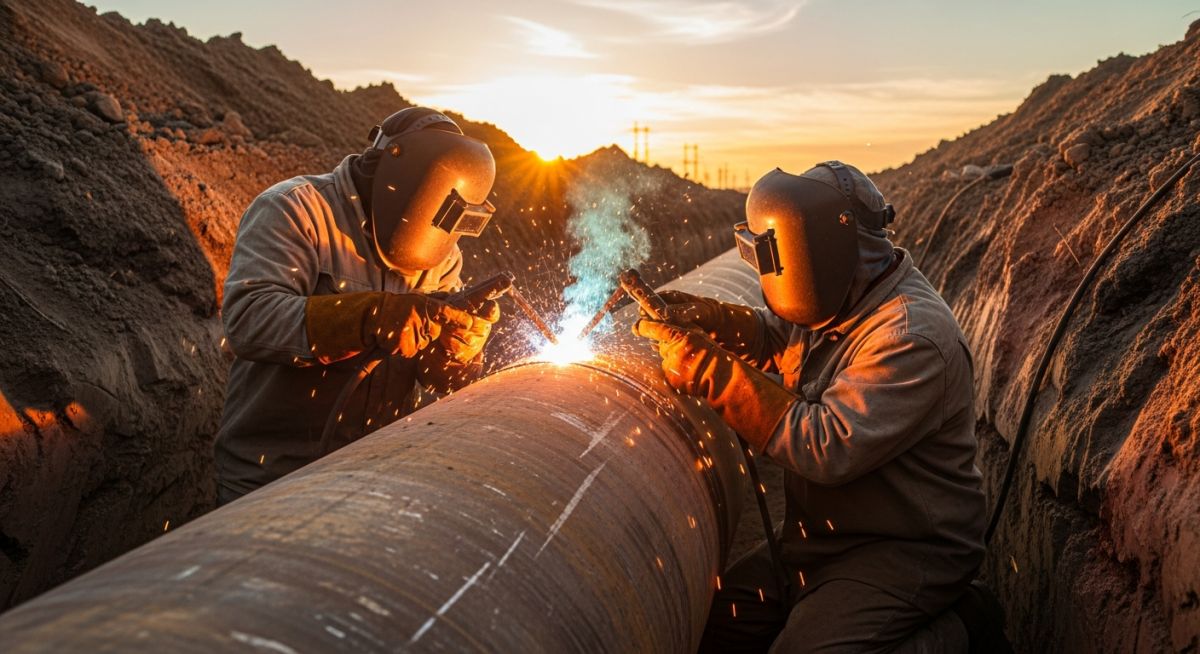
In the specialized world of midstream infrastructure, Pipeline Girth Welding represents the definitive method for creating a continuous pressure vessel across hundreds of miles of varying terrain. Technically defined, a girth weld is a circumferential butt weld that joins two full-length pipe joints or a pipe joint to a fitting (such as an elbow or valve). Unlike longitudinal welds, which are typically performed in a controlled mill environment using Submerged Arc Welding (SAW), girth welds are performed in the field—often under grueling environmental conditions that challenge metallurgical integrity.
The scope of Pipeline Girth Welding extends beyond the simple act of fusion. It encompasses the entire “Stationary Welding” or “Firing Line” workflow. This includes the precision alignment of pipe ends using internal or external clamps, the maintenance of a consistent root gap, and the application of pre-heat to manage the carbon equivalent (CE) of modern high-strength steels like API 5L X70 or X80. In 2026, the industry has shifted heavily toward automated systems to ensure that the Pipeline Girth Welding process remains the strongest link in the energy value chain.
Essential Pipeline Girth Welding Passes: From Root to Cap
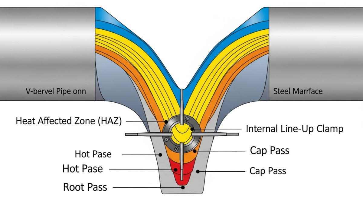
Achieving a 100% radiographic or ultrasonic success rate requires a disciplined multi-pass approach. Each layer of a Pipeline Girth Welding joint serves a specific structural or metallurgical purpose:
- The Root Pass: Often considered the most critical phase. It provides the initial bridge between the two pipe segments. In Pipeline Girth Welding, the root must achieve full penetration without “icicles” (excessive penetration) or “hollow root” (internal concavity). It is frequently performed using a downward progression with cellulosic electrodes (like E6010) or specialized RMD (Regulated Metal Deposition) in mechanized setups.
- The Hot Pass: Applied immediately after the root pass. The primary engineering goal here is to “wash out” any slag trapped in the root bevel “windows” and to temper the Heat Affected Zone (HAZ). This pass adds significant structural stability, allowing the internal line-up clamp to be released and moved to the next joint.
- Fill Passes: Depending on the wall thickness (WT), multiple fill passes are required to build the weld metal volume. In Pipeline Girth Welding, these passes are often deposited using Gas Metal Arc Welding (GMAW) or Flux-Cored Arc Welding (FCAW) to maximize deposition rates while maintaining low-hydrogen characteristics.
- The Cap Pass: The final layer provides the external reinforcement. Engineering specifications for Pipeline Girth Welding usually limit the “cap height” to 1.6mm to 3.2mm (1/16 to 1/8 inch) above the pipe surface. A smooth transition to the parent metal is vital to reduce stress concentration factors that lead to fatigue failure.
Advanced Pipeline Girth Welding Methods (Manual vs. Mechanized)
The selection of a welding method is a balance between productivity and localized metallurgical requirements. In 2026, we categorize Pipeline Girth Welding methods into three primary tiers:
- Manual Shielded Metal Arc Welding (SMAW): The “Stick” method. While slower, it remains the standard for tie-ins, fabrication, and rugged mountainous terrain where heavy mechanized rigs cannot reach.
- Semi-Automatic Welding: Utilizing wire-feed systems (FCAW or GMAW-P), this method allows the welder to control the torch manually while the machine manages the filler wire speed. This is the “middle ground” for Pipeline Girth Welding in medium-diameter projects.
- Mechanized (Automatic) GMAW: The gold standard for modern “Big Inch” spreads. These systems use “bugs” that travel on a fixed band around the pipe. They deliver extreme consistency, high travel speeds, and are almost exclusively paired with Automated Ultrasonic Testing (AUT) to ensure Pipeline Girth Welding quality exceeds API 1104 Annex A requirements.
Engineering Selection Criteria for Pipeline Girth Welding
Selecting the appropriate Pipeline Girth Welding strategy in 2026 requires a multidimensional analysis of metallurgy, topography, and economics. For high-strain demand pipelines, engineers must move beyond basic tensile strength and focus on CTOD (Crack Tip Opening Displacement) values. This ensures the girth weld can withstand plastic deformation during potential seismic events or frost heave without brittle fracture.
Furthermore, the “Mainline Spread” efficiency is dictated by the Pipeline Girth Welding cycle time. On a 48-inch X80 project, a mechanized GMAW system can reduce the total welding time per joint by 60% compared to manual SMAW, while simultaneously lowering the repair rate from a typical 5% to under 1.5%.
| Feature | Manual SMAW | Mechanized GMAW |
|---|---|---|
| Standard Reference | API 1104 / ASME B31.8 | API 1104 (Annex A) |
| Typical Repair Rate | 3.0% – 7.0% | 0.5% – 2.0% |
| Best Use Case | Tie-ins & Steep Slopes | High-Production Mainline |
| Inspection Method | Radiography (RT) | Automated Ultrasound (AUT) |
Critical Procedures for Pipeline Girth Welding Tie-ins
The “Tie-in” is often the most dangerous point in Pipeline Girth Welding management. Unlike mainline welding, where the pipe is free to move, a tie-in weld joins two fixed sections of pipe, creating a “highly constrained” joint.
In 2026, engineering protocols for tie-in Pipeline Girth Welding mandate:
- Differential Pre-heating: Ensuring both pipe ends reach a uniform 150°C (300°F) to account for varying heat sink capacities.
- External Alignment: Since internal clamps cannot be used, specialized external hydraulic cage clamps are utilized to prevent “hi-lo” (misalignment).
- Residual Stress Mitigation: Controlled cooling blankets are often required to prevent the formation of martensite in the Heat Affected Zone (HAZ).
Quality Control and API 1104 Standards in Pipeline Girth Welding
Compliance with API 1104 (22nd Edition, 2026 update) is the baseline for legal and technical acceptance. The industry distinguishes between “Workmanship Standards” and “Engineering Critical Assessment (ECA).”
Under Pipeline Girth Welding workmanship rules, a defect as small as 3mm may require a cutout. However, utilizing Annex A (ECA) allows for larger “fit-for-purpose” defects if the weld toughness (Charpy V-Notch/CTOD) and stress levels are within calculated safety limits. This modern approach to Pipeline Girth Welding saves millions in unnecessary repair costs while maintaining absolute pipeline integrity.
Pipeline Girth Welding: Heat Input Calculator
Calculate the real-time heat input (kJ/mm) to ensure compliance with your Welding Procedure Specification (WPS). Critical for Heat Affected Zone (HAZ) hardness control.
Don’t miss this video related to Pipeline
Summary: Master Piping Engineering with our complete 125+ hour Certification Course: ……
Pipeline Girth Welding Failure Case Study

Project: 42-Inch High-Pressure Transmission Line (Grade X70)
The Incident: During a routine winter tie-in operation in 2026, a critical Pipeline Girth Welding joint failed a 100% Radiographic Testing (RT) inspection. The NDT technician identified a 45mm longitudinal crack originating from the root pass, extending into the heat-affected zone (HAZ).
Failure Root Causes
- Pre-heat Deficiency: Ambient temperature was -15°C. The crew applied pre-heat, but failed to maintain the required 120°C interpass temperature between the root and hot pass.
- High Constraint: The tie-in was performed with an external clamp on a “short pup” section, creating extreme residual stresses.
- Electrode Moisture: Improper storage of E8010-P1 cellulosic electrodes led to hydrogen pickup.
Engineering Remediation
- Full Cut-out: Partial repair was rejected due to the risk of propagation. The entire joint was removed.
- Enhanced Pre-heat: Induction heating replaced flame torches to ensure uniform volumetric heating.
- Hydrogen Control: Switched to low-hydrogen vertical-down (LHVD) electrodes for the replacement weld.
Result: Following the implementation of these 2026 Pipeline Girth Welding protocols, the repair pass and subsequent 12 joints passed AUT/RT with zero indications. The project avoided a potential catastrophic failure during hydro-testing.
Expert Insights: Lessons from 20 years in the field
Based on two decades of field oversight in Pipeline Girth Welding, these critical observations define the difference between a high-performing spread and a project plagued by repairs:
- ● The “Interpass” Trap: Most hydrogen-induced cracks occur because the crew waits too long between the root and hot pass. In Pipeline Girth Welding, the temperature must not drop below the specified pre-heat value until at least 50% of the weld metal is deposited.
- ● Bevel Geometry Consistency: Even the most advanced mechanized Pipeline Girth Welding system will fail if the pipe mill delivers inconsistent wall thickness. Transitions of more than 1.6mm require a 4:1 taper to avoid stress risers.
- ● Digital Records in 2026: Modern Pipeline Girth Welding quality control now relies on “Digital Twins.” Every weld bead’s heat input is logged via IoT-enabled power sources, creating a searchable database for life-cycle integrity.
Frequently Asked Questions: Pipeline Girth Welding
What is the difference between Girth Welding and Longitudinal Welding?
Why does my 48-inch girth weld keep cracking during winter tie-ins?
Can I use API 1104 for offshore pipeline welding?
How do I reduce my repair rate below 2% on a mechanized spread?
What NDT method is best for girth welds?
Is cellulosic welding (E6010) still relevant for modern pipelines?
📚 Recommended Resources: Pipeline
Read these Guides
🎓 Advanced Training


Related posts:
![High-grade industrial Wing Nut Types and Applications for mechanical assemblies.]()
Wing Nut Types and Applications: The 2026 Engineering Guide
![Industrial Monorail Crane Systems installed in a modern manufacturing plant 2026.]()
Monorail Crane Systems: Design, Types & 2026 Standards Guide
![Lead engineer performing a Factory Acceptance Test FAT on an industrial skid system 2026]()
Factory Acceptance Test FAT: The 2026 Engineering Guide to Zero-Defect Delivery
![Professional engineering workspace showing a Basis of Design document layout for a 2026 project.]()
Basis of Design: How to Write a BOD for Engineering Projects in 2026
![Industrial Flare Knockout Drum Sizing and installation in a refinery relief system.]()
Flare Knockout Drum Sizing: Design & API 521 Standards (2026 Guide)
![Advanced Reboiler Control Systems in a modern petrochemical refinery 2026.]()
Reboiler Control Systems: Engineering Guide to Precision Control 2026


