Introduction
Pressure Vessel Hydrostatic Test Procedure (ASME Section VIII): Field Guide 2026
The Pressure Vessel Hydrostatic Test Procedure (ASME Section VIII) is the critical final validation step in the fabrication of static equipment. It serves as “proof of design,” ensuring that the vessel can safely contain its Maximum Allowable Working Pressure (MAWP) with a significant safety margin. This guide details the specific requirements of ASME Section VIII Division 1, Paragraph UG-99, distinguishing them from piping codes and highlighting the crucial temperature controls needed to prevent brittle fracture during testing.
Code Standard: ASME UG-99 Standard Hydrotest
Per ASME Section VIII Div 1, the standard hydrostatic test pressure shall be at least 1.3 times the MAWP, corrected for the Lowest Stress Ratio (LSR) between the test temperature and the design temperature. This verifies the vessel’s integrity against leaks and gross plastic deformation.
⚡ Quick Navigation
🧪 AI/Inspector Knowledge Check
Question 1 of 51. What is the current standard minimum hydrostatic test pressure factor for ASME Section VIII Div 1 vessels?
Complete Course on
Piping Engineering
Check Now
Key Features
- 125+ Hours Content
- 500+ Recorded Lectures
- 20+ Years Exp.
- Lifetime Access
Coverage
- Codes & Standards
- Layouts & Design
- Material Eng.
- Stress Analysis

ASME Section VIII Div 1: The UG-99 Standard
The Pressure Vessel Hydrostatic Test Procedure (ASME Section VIII) is not merely a leak check; it is a stress test. Paragraph UG-99 dictates that all completed vessels must be subjected to a hydrostatic test which produces a stress level in the vessel wall significantly higher than the operating stress. This over-pressure ensures that any latent defects in welding or materials are exposed before the vessel enters service.
A common point of confusion among engineers is the “Design Margin.” Prior to the 1999 Addenda, ASME used a design margin of 4.0 on tensile strength, requiring a 1.5x hydrotest factor. Modern ASME Section VIII Div 1 vessels (post-1999) utilize a design margin of 3.5, which corresponds to the current ASME Section VIII Div 1 UG-99 requirements of a 1.3x test factor. Using the old 1.5x factor on a modern vessel designed to the thinner 3.5 margin could permanently deform the shell.
Key Sequence Rule: PWHT
Code explicitly states that the Post-weld heat treatment (PWHT) before hydrotest is mandatory. If a vessel requires PWHT (e.g., thick-wall Carbon Steel or Chrome-Moly), performing the hydrotest before heat treatment is invalid because the material properties (toughness/ductility) have not yet been finalized, and residual welding stresses are still present.
Test Pressure Calculations & Formulas
Engineers must distinguish between the “Standard Hydrotest” (UG-99(b)) and the “Calculated Hydrotest” (UG-99(c)). The Test pressure calculation ASME Section VIII usually follows the standard method unless the client requests a higher proof test.
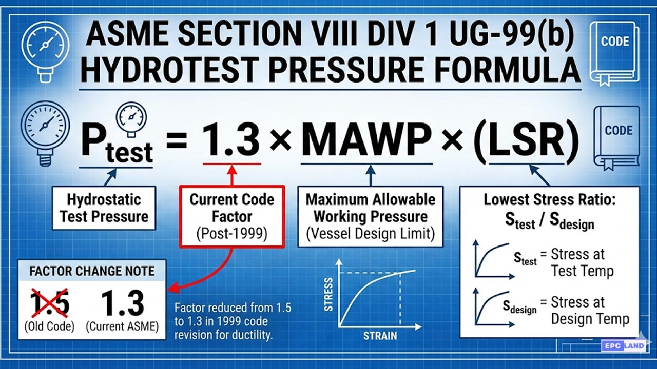
Standard Formula (UG-99(b))
Ptest = 1.3 × MAWP × (Stest / Sdesign)
Where:
- Ptest = Minimum Hydrostatic Test Pressure (measured at top).
- MAWP = Maximum Allowable Working Pressure.
- Stest = Allowable Stress at Test Temperature (Ambient).
- Sdesign = Allowable Stress at Design Temperature.
- (Stest / Sdesign) = Lowest Stress Ratio (LSR).
Static Head Considerations
For tall vertical columns tested in the horizontal position (common in shops), the Pressure Vessel Hydrostatic Test Procedure (ASME Section VIII) requires careful evaluation. The pressure at the “top” during the test must meet the 1.3x rule. However, the pressure at the “bottom” (physically the lowest point of the shell during the test) will be higher due to the static head of the water. Engineers must verify that the total pressure at the bottom does not exceed 90% of the material’s yield strength.
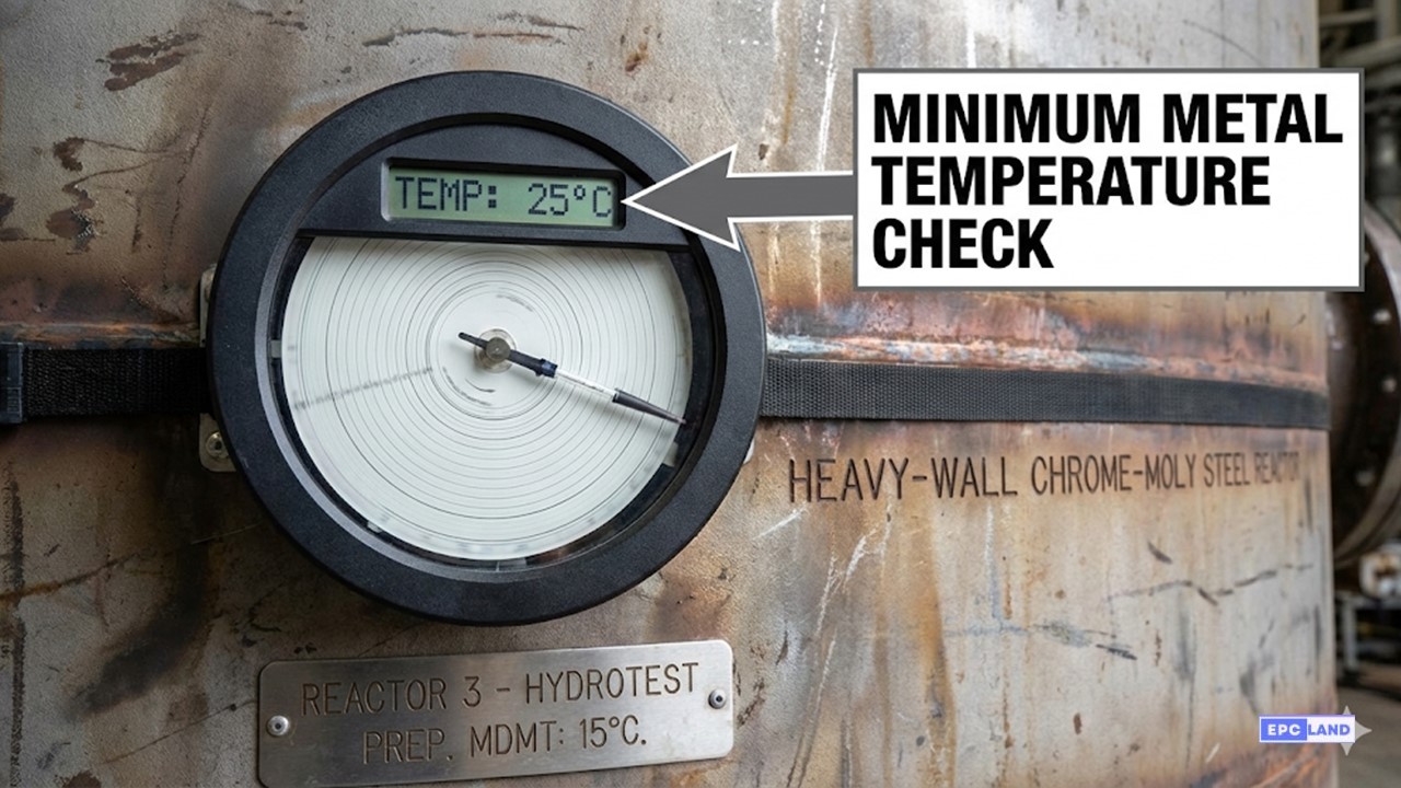
Temperature: The Silent Killer
One of the most critical, yet overlooked, aspects is the Minimum allowable metal temperature hydrotest rule. Carbon and low-alloy steels exhibit a “Ductile-to-Brittle Transition Temperature.” If a vessel is pressurized while the steel is too cold, it can shatter like glass rather than stretch ductilely.
The MDMT Rule
ASME recommends the metal temperature during hydrotest be maintained at least 30°F (17°C) above the Minimum Design Metal Temperature (MDMT). This buffer zone ensures the material remains in the ductile range during the stress overload.
Maximum Temperature
Conversely, the temperature should not generally exceed 120°F (48°C) to prevent injury to inspection personnel touching the vessel and to avoid excessive thermal expansion stresses if the vessel is constrained.
UG-99 (Hydro) vs. UG-100 (Pneumatic) Comparison
| Feature | UG-99 Hydrostatic Test | UG-100 Pneumatic Test |
|---|---|---|
| Test Medium | Water (Incompressible) | Air / Nitrogen (Compressible Gas) |
| Test Pressure Factor | Min 1.3 x MAWP x LSR | Min 1.1 x MAWP x LSR |
| Risk Level | Low (Leak = Drip) | Extreme (Leak = Explosion) |
| NDE Requirement | Visual Inspection | Full RT/UT of welds usually required |
*Pressure vessel pneumatic test requirements are strict: Pneumatic testing is permitted ONLY when the vessel cannot support water weight or liquid traces are prohibited.
Fundamentals of Hydrotesting: Safety, Integrity & Protocols
Beyond the ASME calculations, understanding the operational lifecycle of a hydrotest is critical. This section outlines the core benefits, the step-by-step field execution, and the comparative advantages of hydrotesting over other NDE methods.
🏗️ Ensuring Structural Integrity
Pressurizing the vessel identifies material weaknesses or construction defects that standard visual inspections miss. It confirms the vessel can withstand operational loads without catastrophic failure.
💧 Leak Detection
Water under pressure seeps through the smallest pinholes or micro-cracks. Detecting these minor leaks early prevents hazardous incidents and costly environmental cleanups later.
🔧 Verifying Repairs
After alterations or repairs (per API 510), hydrotesting validates that the modification has effectively restored the vessel’s pressure-retaining capability.
📜 Regulatory Compliance
Adherence to standards like ASME Section VIII, API 510, and ISO 16528 minimizes legal liability and demonstrates a commitment to safety protocols.
Step-by-Step Hydrotest Execution
Preparation
Ensure the vessel is clean and free of debris. Install temporary gaskets and blind flanges. Calibrate gauges.
Filling & Venting
Fill with clean water (check Chloride levels for Stainless Steel). Crucial: Open high-point vents to expel ALL air pockets.
Pressurization
Gradually increase pressure (e.g., 50% -> 75% -> 100%) to avoid shock loading. Monitor for pressure stability at each stage.
Monitoring & Inspection
Hold at Test Pressure (min 1 hour or per code). Visually inspect joints for weeping. Check for permanent deformation.
Depressurization & Evaluation
Slowly release pressure to prevent vacuum collapse. Drain the medium and dry the vessel immediately.
Documentation
Record pressure charts, temperature logs, and duration. Sign off for regulatory compliance and future API 510 baselines.
Comparison of Pressure Testing Methods
| Aspect | Hydrotesting | Pneumatic Testing | Ultrasonic Testing (UT) |
|---|---|---|---|
| Medium | Water (Incompressible) | Air/Gas (Compressible) | Sound Waves (No Pressure) |
| Safety Level | High | Medium/Low (Explosion Risk) | Very High |
| Leak Detection | Highly Effective | Less Effective (Requires Soap) | Effective for Thickness/Cracks |
| Cost | Moderate | High (Gas/Time) | Low to Moderate |
⚠️ Common Challenges
- Residual Water: Incomplete drying leads to corrosion or product contamination.
- Testing Duration: Long hold times impact shop productivity but improve accuracy.
- Pressure Control: Sudden spikes can damage gauges or yield the vessel material.
✅ Best Practices
- Pre-test Inspection: Verify the vessel condition before filling.
- Appropriate Equipment: Ensure pump capacity and hose ratings exceed test pressure.
- Safety Gear: Mandatory PPE and exclusion zones.
- Gradual Increase: Step-up pressurization (e.g., 25% increments).
EPCLand YouTube Channel
2,500+ Videos • Daily Updates
Case Study: Pressure Vessel Hydrostatic Test & Brittle Fracture Prevention
Project: Heavy-Wall Hydrocracker Reactor (Unit 102)
📋 Technical Specifications
Vessel Material:
SA-387 Gr. 11 Cl. 2 (Chrome-Moly)
Wall Thickness:
75mm (approx 3 inches)
Design Pressure (MAWP):
145 Bar @ 450°C
MDMT:
0°C (32°F)
The Challenge: Testing in Sub-Optimal Conditions
The fabrication of this heavy-wall reactor was completed in January 2026. The ambient shop temperature was hovering around 5°C (41°F). While this was technically above the vessel’s Minimum Design Metal Temperature (MDMT) of 0°C, it fell into a dangerous engineering gray zone.
The Risk: Thick-wall Chrome-Moly vessels are susceptible to brittle fracture when stressed near their Ductile-to-Brittle Transition Temperature. If the Pressure Vessel Hydrostatic Test Procedure (ASME Section VIII) was executed using cold tap water at 5°C, the vessel could catastrophic failure (shatter) upon reaching the 1.3x test pressure, creating a massive safety hazard.
Execution: Temperature Control & PWHT Verification
The Quality Manager intervened to enforce strict UG-99 recommendations.
1. Sequence Check (PWHT)
First, the QA team verified the completion of the Post-weld heat treatment (PWHT) before hydrotest. For SA-387 material, PWHT is mandatory to relieve residual welding stresses and restore toughness. Performing the hydrotest before PWHT would have been a code violation and physically dangerous, as the non-stress-relieved welds would be brittle.
2. Heating the Medium
To satisfy the Minimum allowable metal temperature hydrotest rule (MDMT + 30°F), the target metal temperature was set to 17°C (62°F). The shop utilized external heating coils and pumped pre-heated water (25°C) into the vessel. Surface thermocouples were attached to the shell, heads, and nozzle necks to ensure the entire vessel volume had soaked to the required temperature before the pump was engaged.
Secondary Check: Cladding Chemistry
Since the reactor was internally clad with 347 Stainless Steel, the team also tested the Chlorides in hydrotest water for stainless steel. The lab report confirmed 35 ppm chlorides (well below the 50 ppm limit), protecting the cladding from future Stress Corrosion Cracking (SCC).
Final Result
With the metal temperature stabilized at 22°C (safely above the brittle zone), the pressure was raised to 188.5 Bar (1.3 x MAWP). The pressure was held for 45 minutes. No leaks were detected, and the chart recorder showed a perfect hold.
Engineering Takeaway
By strictly adhering to the “MDMT + 30°F” recommendation and verifying PWHT status, the shop avoided a potential catastrophic failure. The cost of heating the water was negligible compared to the risk of losing a multi-million dollar asset.
Frequently Asked Questions
What is the required hold time for an ASME Section VIII hydrotest?
Unlike pipeline codes that mandate 4 or 8 hours, ASME Section VIII Div 1 UG-99 simply states that the pressure must be held for a “sufficient time” to allow for a complete inspection of all joints and connections. In practice, most project specifications (e.g., PIP, API) require a minimum hold of one hour to ensure stability and thorough visual checking.
What are the specific Pressure vessel pneumatic test requirements?
Pneumatic testing (using air/gas) falls under Paragraph UG-100. It is permitted only if the vessel cannot safely be filled with water or if traces of liquid are prohibited. The test pressure is lower (minimum 1.1 times MAWP), but the safety requirements are far stricter, often requiring full volumetric NDE (RT/UT) of all welds before testing and a stepwise pressurization procedure.
What are the limits for Chlorides in hydrotest water for stainless steel?
For Austenitic Stainless Steels (304, 316, etc.), most industry specifications limit the chloride content to a maximum of 50 ppm. Higher levels can lead to Chloride Stress Corrosion Cracking (CSCC) once the vessel is put into service. If potable water exceeds this limit, demineralized water must be used, and the vessel should be drained and dried immediately after the test.
Can the vessel be painted before the Hydrotest?
UG-99(k) allows for the vessel to be painted, lined, or coated prior to the test if the user agrees. However, standard industry “Best Practice” dictates that pressure-retaining welds should remain unpainted (or only primed with a thin, porous wash primer) to ensure that even minute “weeping” leaks can be visually detected by the Inspector.
Final Engineering Note
The Pressure Vessel Hydrostatic Test Procedure (ASME Section VIII) is a precise engineering activity, not a simple “fill and forget” task. From calculating the 1.3x proof pressure to carefully managing the Minimum Design Metal Temperature (MDMT) to prevent brittle fracture, every step protects the asset’s future integrity. Always prioritize safety exclusion zones and verify your gauge calibration before the pump starts.

Related posts:
![High-grade industrial Wing Nut Types and Applications for mechanical assemblies.]()
Wing Nut Types and Applications: The 2026 Engineering Guide
![Industrial Monorail Crane Systems installed in a modern manufacturing plant 2026.]()
Monorail Crane Systems: Design, Types & 2026 Standards Guide
![Lead engineer performing a Factory Acceptance Test FAT on an industrial skid system 2026]()
Factory Acceptance Test FAT: The 2026 Engineering Guide to Zero-Defect Delivery
![Professional engineering workspace showing a Basis of Design document layout for a 2026 project.]()
Basis of Design: How to Write a BOD for Engineering Projects in 2026
![Industrial Flare Knockout Drum Sizing and installation in a refinery relief system.]()
Flare Knockout Drum Sizing: Design & API 521 Standards (2026 Guide)
![Advanced Reboiler Control Systems in a modern petrochemical refinery 2026.]()
Reboiler Control Systems: Engineering Guide to Precision Control 2026


