Heat Exchanger Fouling Factor: Its Significance and Calculation
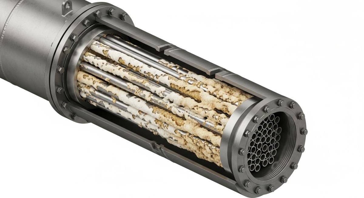
The Heat Exchanger Fouling Factor represents the specific thermal resistance introduced by the accumulation of unwanted deposits—such as scale, corrosion products, or biological growth—on the heat transfer surfaces of industrial equipment. In 2026, understanding this variable is critical for maintaining the Overall Heat Transfer Coefficient and ensuring long-term operational efficiency.
What is the Heat Exchanger Fouling Factor?
The Heat Exchanger Fouling Factor (represented as Rd or Rf) is a measure of the additional thermal resistance caused by deposit build-up on tube surfaces. It is mathematically defined as the difference between the reciprocal of the dirty overall heat transfer coefficient and the reciprocal of the clean coefficient.
Technical Knowledge Check
Question 1 of 5Quiz Complete!
Complete Course on
Piping Engineering
Check Now
Key Features
- 125+ Hours Content
- 500+ Recorded Lectures
- 20+ Years Exp.
- Lifetime Access
Coverage
- Codes & Standards
- Layouts & Design
- Material Eng.
- Stress Analysis
What is the Heat Exchanger Fouling Factor?
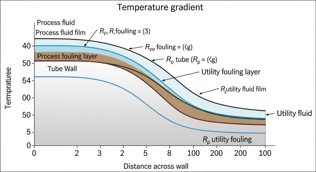
In the field of thermal engineering, the Heat Exchanger Fouling Factor (Rd) represents the accumulation of undesirable material on the heat transfer surfaces. This layer acts as an additional thermal insulator, impeding the flow of heat between two fluids. By 2026 standards, accurate quantification of this factor is mandatory for process safety and performance optimization in petrochemical and power generation facilities.
Defining Thermal Resistance and Scale Build-up
The Scale Build-up on heat transfer surfaces creates a conductive resistance that can be compared to an electrical resistor in a circuit. According to ASME and TEMA standards, Thermal Resistance is not a static value; it evolves over time as particles precipitate, crystallize, or corrode the tube walls. This progression leads to a steady decline in the Overall Heat Transfer Coefficient.
Significance of the Heat Exchanger Fouling Factor in Industrial Systems
The economic and operational implications of fouling are profound. Neglecting the Heat Exchanger Fouling Factor during the design phase can lead to equipment failure or significant energy waste.
Performance Evaluation and Overall Heat Transfer Coefficient
The Overall Heat Transfer Coefficient (U) is the primary metric for heat exchanger health. As fouling increases, U decreases, requiring either higher temperature driving forces or reduced flow rates to maintain process targets.
Energy Efficiency Analysis and Heat Exchanger Efficiency
Maintaining high Heat Exchanger Efficiency is vital for carbon footprint reduction in 2026. Fouling forces pumps and compressors to work harder to overcome pressure drops, directly increasing operational costs in USD.
Equipment Sizing for TEMA Fouling Resistance
When engineers specify a new unit, they refer to TEMA Fouling Resistance tables. These tables provide empirical values that allow for "oversizing" the heat exchanger. An appropriately oversized unit accounts for the Heat Exchanger Fouling Factor that will inevitably develop between cleaning cycles, ensuring the unit meets its duty even when dirty.
Maintenance Planning and Reliability-Centered Monitoring
By tracking the Heat Exchanger Fouling Factor in real-time, maintenance teams can move from reactive to predictive cleaning. This reliability-centered approach uses API inspection codes to determine the optimal interval for hydro-blasting or chemical cleaning, preventing unscheduled shutdowns.
Methods for Calculating the Heat Exchanger Fouling Factor
Determining the exact value of the Heat Exchanger Fouling Factor requires comparing field performance data against original clean design specifications.
LMTD (Log Mean Temperature Difference) Correction Method
The Log Mean Temperature Difference (LMTD) method is the most common industrial approach. It involves calculating the heat duty (Q) and then solving for the dirty overall heat transfer coefficient (Ud) using the equation Q = Ud * A * LMTD. The difference between the clean and dirty coefficients reveals the fouling resistance.
ε-NTU (Effectiveness-Number of Transfer Units) Method
When inlet and outlet temperatures are not fully known, the ε-NTU Method provides a robust alternative for determining the Heat Exchanger Fouling Factor. This method relates the Heat Exchanger Efficiency (effectiveness) to the Heat Capacity Ratio and the Number of Transfer Units (NTU). In 2026, automated DCS systems use this logic to calculate real-time degradation in complex plate-fin or spiral exchangers.
Monitoring and Empirical Data Acquisition
Empirical data acquisition involves the installation of high-precision pressure transducers and thermocouples. By monitoring the increase in pressure drop (ΔP) alongside the Heat Exchanger Fouling Factor, engineers can differentiate between "soft" fouling (bio-slimes) and "hard" fouling (calcium carbonate scaling).
Critical Factors Affecting the Heat Exchanger Fouling Factor
The rate at which the Heat Exchanger Fouling Factor increases depends on several thermodynamic and chemical variables. Proper management of these factors is essential to maintain Overall Heat Transfer Coefficient stability.
| Factor | Effect on Fouling Factor | Engineering Mitigation |
|---|---|---|
| Fluid Velocity | High velocity decreases fouling | Design for minimum 1.0 m/s (tubeside) |
| Temperature | High wall temp increases scaling | Limit skin temperature below saturation |
| Surface Finish | Roughness promotes adhesion | Use electropolished or coated tubes |
Fluid Composition and Precipitation Fouling
Precipitation fouling occurs when dissolved salts (like CaSO4) reach their solubility limit at the hot tube wall. This is a primary driver of the Heat Exchanger Fouling Factor in cooling water services.
Operating Time and the Induction Period
The growth of the Heat Exchanger Fouling Factor often follows an asymptotic curve. The "Induction Period" is the initial timeframe where the surface remains clean before a rapid Scale Build-up occurs.
Heat Exchanger Fouling Factor Formula and Derivations
The Fundamental Resistance Equation
Rd = (1 / Ud) - (1 / Uc)
Rd = Heat Exchanger Fouling Factor (m2K/W)
Ud = Overall Heat Transfer Coefficient - Fouled/Dirty Condition (W/m2K)
Uc = Overall Heat Transfer Coefficient - Clean Condition (W/m2K)
In detailed 2026 design simulations, the total Heat Exchanger Fouling Factor is actually the sum of the internal (Rdi) and external (Rdo) resistances, adjusted for the surface area ratio:
Rtotal = Rdi(Ao/Ai) + Rdo
Typical Heat Exchanger Fouling Factor Values for Design
Engineering contractors utilize TEMA Fouling Resistance tables to select appropriate design margins. Below are the 2026 industry standards for common process fluids.
| Fluid Type | Standard Rd (m2K/W) | Fouling Severity |
|---|---|---|
| Distilled Water | 0.0001 | Low |
| Treated Cooling Water | 0.0002 - 0.0004 | Moderate |
| Sea Water (<50°C) | 0.0005 | High |
| Fuel Oil / Heavy Crude | 0.0009 - 0.0020 | Very High |
Heat Exchanger Fouling Factor Calculator
Use this 2026 engineering tool to determine the current fouling resistance based on your observed Overall Heat Transfer Coefficients.
Obtain this from the original 2026 manufacturer datasheet.
Calculated from current field temperature and flow data.
Calculated Heat Exchanger Fouling Factor (Rd):
Unit: m2K/W
Don't miss this video related to Heat Exchanger
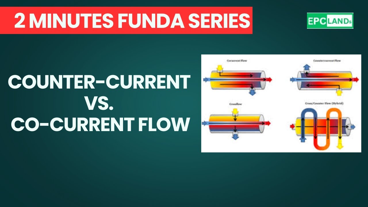
Summary: How do you get the most efficient heat transfer? It's all about the flow direction! This video explains the difference between ......
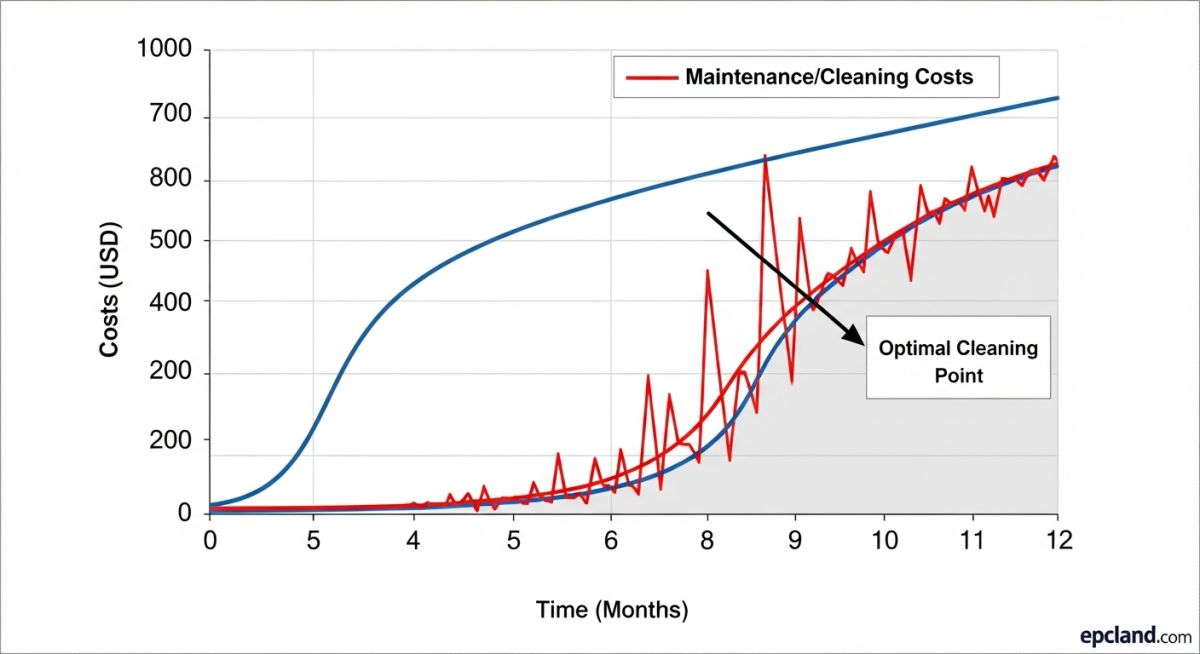
Economic Modeling: The Cost of the Heat Exchanger Fouling Factor
The impact of the Heat Exchanger Fouling Factor extends far beyond thermal efficiency; it is a critical financial liability. In 2026, engineers utilize rigorous economic models to balance Capital Expenditure (CapEx) against Operational Expenditure (OpEx), fundamentally asking: *Is it cheaper to run a dirty exchanger or stop production to clean it?*
Operational Expense (OpEx) Analysis: The Energy Penalty in USD
As the Overall Heat Transfer Coefficient (Ud) declines due to Scale Build-up, pumps and compressors must consume more electricity to maintain process flow and temperature differentials. This energy penalty is measured directly in USD per day of operation. A typical mid-sized refinery might lose upwards of 50,000 USD daily in excess fuel costs due to an elevated Heat Exchanger Fouling Factor.
Capital Expense (CapEx) vs. TEMA Fouling Resistance
Design engineers mitigate future OpEx through initial CapEx: building a physically larger heat exchanger to incorporate a higher design Heat Exchanger Fouling Factor (a larger safety margin). TEMA Fouling Resistance values are used to calculate the required oversized surface area.
The optimal design point minimizes the Net Present Value (NPV) of the entire lifecycle cost, ensuring compliance with ISO and ASME standards while delivering maximum return on investment. Modern 2026 simulation tools incorporate volatility in energy prices to make these projections more accurate.
Case Study: Impact of Heat Exchanger Fouling Factor on Refinery Production
In early 2026, a major refinery facility faced a critical production bottleneck in its heavy crude preheat train. The primary cause was a rapid, unpredicted rise in the Heat Exchanger Fouling Factor, which compromised the system thermal efficiency and increased the furnace load beyond its design capacity.
Project Data & Failure Analysis
-
✔
Equipment Type: High-pressure Shell and Tube Exchanger (TEMA Class R).
-
✔
Baseline Design Rd: 0.0004 m2K/W.
-
✔
Peak Observed Rd: 0.0022 m2K/W.
-
✔
Failure Root Cause: Asphaltene precipitation triggered by high tube-wall skin temperatures, leading to "coking" and irreversible scale build-up.
-
✔
Economic Loss: Estimated at 125,000 USD per day due to increased fuel consumption in the fired heater.
Engineering Fix & 2026 Results
The engineering team implemented a multi-faceted remediation strategy centered on restoring the Overall Heat Transfer Coefficient and stabilizing the boundary layer chemistry.
Technical Solutions:
Implementation of automated chemical dispersant injection and an upgrade to "Enhanced Surface" tubes to increase wall shear stress.
- Induction Period Extension: Increased from 3 weeks to 5 months.
- Cleaning Frequency: Reduced from twice per year to once every two years.
- Energy Savings: 12 percent reduction in total CDU fuel gas consumption.
Lessons Learned
The primary takeaway from this 2026 refinery audit is that the Heat Exchanger Fouling Factor must be treated as a dynamic operational parameter rather than a static design margin. Static TEMA values often fail to account for the complex chemical interactions of modern crude slates. By integrating real-time Rd monitoring with the facility's digital twin, engineers were able to transition from reactive maintenance to a high-reliability, condition-based cleaning schedule.
Frequently Asked Questions (FAQ)
How can I reduce the Heat Exchanger Fouling Factor in cooling water systems?
What is the difference between fouling resistance and the fouling factor?
How does the Heat Exchanger Fouling Factor affect hydraulic pressure drop?
When should a heat exchanger be cleaned based on the fouling factor?
📚 Recommended Resources: Heat Exchanger
Read these Guides
🎓 Advanced Training


Related posts:
![High-grade industrial Wing Nut Types and Applications for mechanical assemblies.]()
Wing Nut Types and Applications: The 2026 Engineering Guide
![Industrial Monorail Crane Systems installed in a modern manufacturing plant 2026.]()
Monorail Crane Systems: Design, Types & 2026 Standards Guide
![Lead engineer performing a Factory Acceptance Test FAT on an industrial skid system 2026]()
Factory Acceptance Test FAT: The 2026 Engineering Guide to Zero-Defect Delivery
![Professional engineering workspace showing a Basis of Design document layout for a 2026 project.]()
Basis of Design: How to Write a BOD for Engineering Projects in 2026
![Industrial Flare Knockout Drum Sizing and installation in a refinery relief system.]()
Flare Knockout Drum Sizing: Design & API 521 Standards (2026 Guide)
![Advanced Reboiler Control Systems in a modern petrochemical refinery 2026.]()
Reboiler Control Systems: Engineering Guide to Precision Control 2026


