Creep Rupture Usage Factor for Allowable Variations in Elevated Temperature Service
The Creep Rupture Usage Factor is a critical dimensionless value used by mechanical engineers to quantify the life consumption of components operating in the creep regime. By applying Robinson’s Rule, engineers can determine how much of a material’s design life has been exhausted during pressure and temperature variations.
What is the Creep Rupture Usage Factor?
The Creep Rupture Usage Factor is the ratio of actual operating time at a specific stress and temperature to the total time-to-rupture at those same conditions. In engineering standards like ASME BPVC, the total cumulative usage factor must not exceed 1.0 (or specific allowable limits like 0.1 for certain variations) to prevent catastrophic failure.

Table of Contents
- 1. What is Creep Rupture Usage Factor and Why is it Critical?
- 2. Engineering Standards for Creep Rupture Usage Factor
- 3. Step-by-Step Calculation of Creep Rupture Usage Factor
- 4. Allowable Variations and Limits in Creep Rupture Usage Factor
- 5. Industrial Case Study: Creep Rupture Usage Factor in Superheater Tubes
Engineering Knowledge Check
Question 1 of 5What is the Creep Rupture Usage Factor in Engineering?
In the demanding landscape of 2026 industrial operations, components like high-pressure steam lines and furnace tubes often operate at temperatures where material deformation becomes time-dependent. The Creep Rupture Usage Factor serves as a quantitative measure of how much of a material’s theoretical life has been consumed by these thermal and mechanical stresses. When a metal is subjected to temperatures exceeding approximately 40% of its absolute melting point, it enters the creep regime, where even stresses below the yield strength can eventually lead to rupture.
Engineers utilize this factor to manage “allowable variations.” In real-world service, pressure and temperature are rarely perfectly static. Whether due to process upsets, seasonal changes, or start-up cycles, these excursions accelerate metallurgical degradation. The usage factor allows for a standardized way to sum these disparate events into a single value to ensure the cumulative damage stays within safe design margins defined by codes like ASME B31.3 and API 579-1/ASME FFS-1.
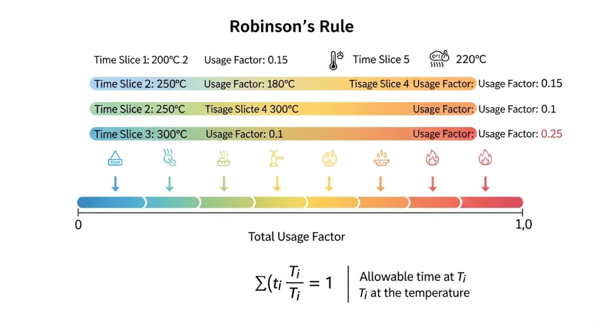
Understanding the Linear Life Fraction Rule and Robinson’s Hypothesis
The Linear Life Fraction Rule, originally proposed by Robinson in 1952, remains the industry standard for cumulative damage assessment in 2026. This hypothesis assumes that the damage sustained during any specific time interval is independent of the damage sustained in other intervals. Essentially, the “fraction” of life used is simply the actual time spent at a specific condition divided by the total time it would take to rupture at that same condition.
According to this rule, the total damage is the linear sum of these individual fractions. While modern research into non-linear damage models exists, the Linear Life Fraction Rule is preferred for its conservative nature and relative simplicity in engineering calculations. It provides the mathematical backbone for the Creep Rupture Usage Factor by defining the “budget” of life available to the component before failure is predicted.
Technical Calculation of Creep Rupture Usage Factor
The Creep Rupture Usage Factor (often denoted as U or f) is calculated by summing the ratios for each discrete operating period. The basic formula is expressed as:
U = Σ (ti / tri)
In this equation:
- ti: The actual duration of the i-th operating condition (e.g., 200 hours at 550 degrees Celsius).
- tri: The rupture life of the material at the specific stress and temperature of that i-th condition.
- Σ: The summation of all intervals across the component’s service history.
Role of the Larson-Miller Parameter in Rupture Life Prediction
To find the value of tri, engineers frequently turn to the Larson-Miller Parameter (LMP). This LSI-standardized correlation relates temperature, time, and stress into a single master curve for a specific alloy. The parameter is typically defined as:
LMP = Tabsolute [ C + log10(tr) ]
By knowing the stress on the component and the operating temperature (Tabsolute), the rupture life (tr) can be solved. In 2026, many computerized asset integrity management systems use pre-programmed LMP constants (C) for common materials like P11, P22, and P91 to automate the Creep Rupture Usage Factor monitoring in real-time.
ASME B31.3 Appendix V Rules for Allowable Stress Variations
The ASME B31.3 code provides a rigorous framework for evaluating short-term excursions in piping systems through Appendix V. In the 2026 edition of the code, these rules dictate how much a system can deviate from its design pressure and temperature without compromising safety. The core requirement is that the Creep Rupture Usage Factor must be calculated for all variations that exceed the design conditions.
According to the code, the total cumulative damage across the entire service life, including all variations, must satisfy the condition where the sum of individual life fractions is less than or equal to 1.0. This ensures that even with operational upsets, the piping does not exceed its metallurgical limits. For engineers in 2026, compliance involves tracking every hour of “over-stress” service and deducting it from the total life “bank” of the material.
| Condition Type | Duration Limit | Creep Rupture Usage Factor Limit |
|---|---|---|
| Normal Operation | Design Life (e.g., 100k – 200k hours) | Calculated as fraction of Tr |
| Short-term Variations | Typically < 10 percent of total time | Sum of all fractions ≤ 1.0 |
| Emergency Excursions | Specific event duration | Must be added to cumulative total |
Assessing Cumulative Damage for Creep Rupture Usage Factor Compliance
Evaluating cumulative damage requires a granular approach to data logging. In modern 2026 facilities, Digital Twins often monitor Creep Rupture Usage Factor consumption by integrating real-time SCADA data. The process involves identifying discrete “bins” of stress and temperature. For each bin, the rupture life (tri) is determined using high-temperature material databases.
Math Note: The Larson-Miller Logic
To solve for tri, we rearrange the LMP formula: log10(tri) = [LMP / Tabs] – C. The temperature Tabs must be in Rankine or Kelvin, and the stress used to find LMP from the master curve must include the variation factor (e.g., 1.15 times design pressure).
Material Sensitivity Analysis: P11 vs. P91 Alloys
Material choice significantly impacts the Creep Rupture Usage Factor. Grade P11 (1.25Cr-0.5Mo) is often used for moderate temperatures but suffers from relatively rapid creep life consumption if temperatures exceed 565 degrees Celsius. In contrast, Grade P91 (9Cr-1Mo-V) possesses a modified microstructure that provides much higher creep strength.
When a P11 pipe and a P91 pipe are both subjected to a 50-degree Celsius excursion, the P11 component might consume 5 percent of its life in just 100 hours, whereas the P91 component might only consume 0.5 percent. This discrepancy highlights why tracking the Creep Rupture Usage Factor is even more critical for older assets or less advanced alloys during process optimization or capacity increases.
Creep Rupture Usage Factor Calculator
Use this tool to calculate the cumulative life consumption based on Robinson’s Linear Life Fraction Rule. Enter the actual operating hours (t) and the theoretical rupture life (Tr) for each variation event.
Cumulative Usage Factor (U)
Don’t miss this video related to Creep

Summary: Master Piping Engineering with our complete 125+ hour Certification Course: ……
Field Verification: NDT Methods for Validating the Creep Rupture Usage Factor
While the Creep Rupture Usage Factor provides a vital mathematical estimate of damage, 2026 engineering best practices dictate that high-risk components must undergo physical validation. Mathematical models assume homogenous material properties and perfectly recorded process data, which may not always reflect the reality of aging infrastructure. Non-Destructive Testing (NDT) acts as the ground-truth for the cumulative damage calculated through the Linear Life Fraction Rule.

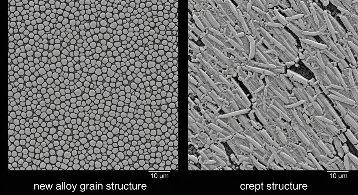
In-Situ Metallographic Replication
Replication is the gold standard for verifying the Creep Rupture Usage Factor in the field. By polishing the metal surface to a mirror finish and taking a “fingerprint” of the microstructure using cellulose acetate film, inspectors can identify the presence of creep cavities. In 2026, automated image analysis software can categorize these cavities into the Neubauer classification system, directly correlating physical micro-voids to the calculated life fraction.
| Neubauer Rating | Microstructural Condition | Correlation to Usage Factor |
|---|---|---|
| Isolated Cavities | Early stage creep damage | U approximately 0.4 to 0.6 |
| Oriented Cavities | Damage aligned with stress direction | U approximately 0.6 to 0.8 |
| Micro-cracks | Coalescence of cavities | U > 0.8 (Replacement Indicated) |
Advanced Ultrasonic Testing (PAUT and TFM)
Phased Array Ultrasonic Testing (PAUT) and Total Focusing Method (TFM) have become essential in 2026 for detecting subsurface creep damage that replication cannot reach. These methods identify “creep fissuring” in the heat-affected zones (HAZ) of welds. When a high Creep Rupture Usage Factor is calculated for a welded header, PAUT is deployed to ensure that no internal cracking has initiated, providing a three-dimensional view of the component’s integrity.
Case Study: Assessing the Creep Rupture Usage Factor in a P91 Main Steam Header
Project Data
- Material: ASTM A335 Grade P91 (9Cr-1Mo-V)
- Design Temperature: 595 degrees Celsius (1103 degrees Fahrenheit)
- Design Pressure: 2,500 PSI
- Service Life: 10 Years (87,600 Operating Hours)
- Excursion Event: 15 percent pressure increase for 4,000 cumulative hours
Assessment Analysis
A fitness-for-service (FFS) audit in 2026 revealed that control valve hunting caused the system to operate at 2,875 PSI periodically. The engineering team was tasked with determining the Creep Rupture Usage Factor to decide if the header required immediate replacement or if the remaining life was sufficient for continued operation until the next planned turnaround.
Engineering Fix and Calculation
Using the Larson-Miller master curve for P91, the rupture life (Tr) at design conditions was determined to be 220,000 hours. At the excursion stress (115 percent of design), the rupture life dropped significantly to 48,000 hours. The cumulative damage was calculated as follows:
| Condition | Actual Time (t) | Rupture Life (Tr) | Life Fraction |
|---|---|---|---|
| Normal Service | 83,600 hrs | 220,000 hrs | 0.380 |
| Excursions | 4,000 hrs | 48,000 hrs | 0.083 |
| Total Creep Rupture Usage Factor (U) | 0.463 | ||
Result: Since U is 0.463 (well below 1.0), the component was cleared for continued service.
Lessons Learned
- Conservative Design: P91 high-creep strength significantly buffered the impact of the excursions.
- Data Integrity: Accurate logging of pressure excursion durations is vital for an accurate Creep Rupture Usage Factor assessment.
- Regulatory Alignment: Documentation must align with the ASME B31.3 Standard guidelines to pass third-party safety audits.
Frequently Asked Questions
How does the Larson-Miller Parameter affect the calculation of the Creep Rupture Usage Factor?
Is Robinson’s Linear Life Fraction Rule applicable to all high-temperature alloys in 2026?
What are the consequences of exceeding the Creep Rupture Usage Factor limit in piping systems?
How does ASME B31.3 Appendix V differentiate between short-term variations and design conditions?
Final Engineering Summary
In 2026, the complexity of high-temperature operations demands a rigorous approach to asset integrity. The Creep Rupture Usage Factor is not merely a theoretical calculation but a vital safety metric that prevents catastrophic failures in power plants, refineries, and chemical facilities. By applying Robinson’s Linear Life Fraction Rule and adhering to ASME B31.3 Appendix V guidelines, engineers can precisely manage the trade-off between operational flexibility and material longevity.
As we advance, the integration of real-time monitoring and advanced material databases will continue to refine how we calculate and track the Creep Rupture Usage Factor, ensuring that our infrastructure remains safe and reliable even under the most demanding thermal conditions.
📚 Recommended Resources: Creep Rupture
Read these Guides

Related posts:
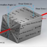
![3D engineering diagram illustrating shear modulus deformation on a solid block with force vectors.]()
Understanding Shear Modulus and Modulus of Rigidity in Piping Design
![3D render of a protective chromium oxide film forming on a stainless steel surface.]()
How Does Stainless Steel Oxide Film Formation Prevent Corrosion?
![Side-by-side comparison of industrial metal casting and metal forging processes.]()
Casting vs Forging: Key Differences for Industrial Piping Systems
![Various types of industrial pumps displayed in a modern engineering facility.]()
Guide to Types of Pumps and Their Working Principles
![3D digital GIS map overlay showing petroleum pipeline routes across a terrain]()
Why GIS in Petroleum and Pipeline Industry is Absolutely Critical
![CAESAR II Version 14 pipe stress analysis software interface displaying a 3D piping model.]()
What Is New in CAESAR II Version 14 Pipe Stress Analysis