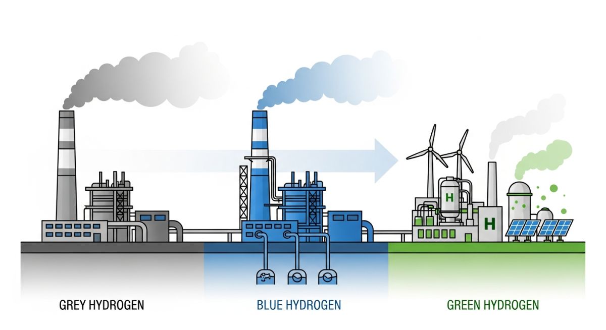
Green vs Blue vs Grey Hydrogen: Complete Engineering Comparison Guide
In my 20+ years of designing piping systems and process plants, I have watched the hydrogen landscape shift from a niche refining feedstock to the absolute center of the global energy transition. For decades, we built steam methane reforming (SMR) units without a second thought about the carbon dioxide venting from the stack. Today, as we transition from grey to blue and green hydrogen, the engineering challenges have multiplied. We are no longer just managing high-temperature hydrogen attack (HTHA); we are now dealing with massive electrolyzer arrays, complex carbon capture solvent loops, and the stringent material requirements of high-pressure hydrogen transport under ASME B31.12. This guide breaks down the technical, economic, and material realities of these three hydrogen pathways from a boots-on-the-ground engineering perspective.
Key Engineering Takeaways
- Grey hydrogen remains the cheapest option but carries a heavy carbon penalty of 9 to 11 kg of CO2 per kg of H2.
- Blue hydrogen integrates carbon capture (CCS) to reduce emissions by 85% to 95%, requiring specialized amine or physical solvent units.
- Green hydrogen utilizes water electrolysis powered by renewable energy, eliminating operational emissions but demanding massive electrical and water treatment infrastructure.
- Material selection is paramount: hydrogen embrittlement requires strict adherence to ASME B31.12, favoring low-carbon stainless steels like 316/316L or controlled-hardness carbon steels.
Analyzing Green vs Blue vs Grey Hydrogen Production Pathways
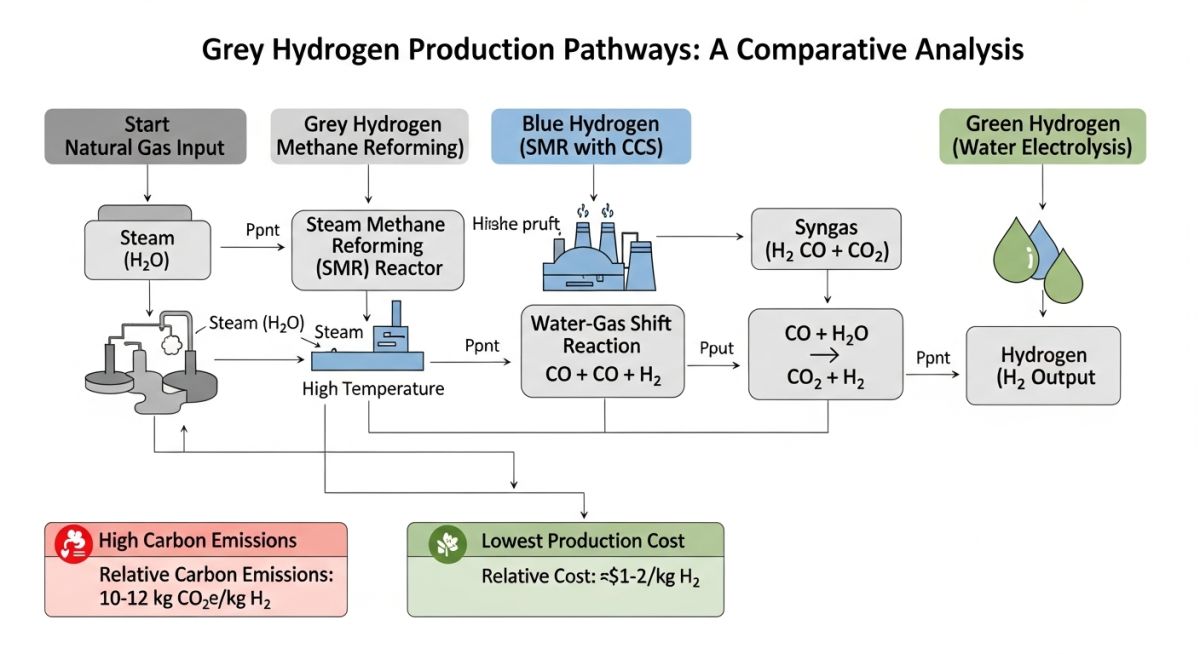
To understand the engineering differences, we must look closely at the chemical reactions and thermodynamic limits of each production method. Grey hydrogen relies on Steam Methane Reforming (SMR), where natural gas reacts with steam at high temperatures (700 to 1000 degrees Celsius) over a nickel catalyst. This reaction produces syngas, which is then processed in a Water Gas Shift (WGS) reactor to maximize hydrogen yield. The primary chemical equations are:
Water Gas Shift: CO + H2O → CO2 + H2 (Exothermic, Delta H = -41 kJ/mol)
Blue hydrogen takes this exact process and adds Carbon Capture and Storage (CCS). Instead of venting the CO2 from the SMR flue gas and the pressure swing adsorption (PSA) tail gas, we route these streams through an absorption column. Amine-based solvents (such as Monoethanolamine or Methyldiethanolamine) or physical solvents (like Selexol) capture the CO2. The solvent is then heated in a regenerator column to release pure CO2, which is compressed to a supercritical state (above 73.8 bar) for pipeline transport and deep geological injection.
Green hydrogen completely departs from fossil fuels. It uses water electrolysis, splitting water molecules into hydrogen and oxygen using renewable electricity. The overall reaction is:
The three dominant electrolyzer technologies are Alkaline, Proton Exchange Membrane (PEM), and Solid Oxide Electrolysis Cells (SOEC). Alkaline systems use a liquid potassium hydroxide (KOH) electrolyte and are highly mature, but they struggle with the dynamic power fluctuations of wind and solar. PEM systems use a solid polymer membrane and respond rapidly to power changes, making them ideal for direct coupling with renewables, though they require expensive noble metals like platinum and iridium. SOEC operates at high temperatures (700 to 850 degrees Celsius), utilizing waste heat to achieve superior electrical efficiency.
Hydrogen atoms are extremely small and easily diffuse into the crystalline lattice of metals, leading to subcritical crack growth and catastrophic brittle failure. When designing piping systems for green, blue, or grey hydrogen, you must strictly limit material hardness to 22 HRC (Rockwell C) and avoid high-strength carbon steels. Always specify low-hydrogen welding practices and perform post-weld heat treatment (PWHT) in accordance with ASME B31.3 and ASME B31.12.
| Parameter | Grey Hydrogen | Blue Hydrogen | Green Hydrogen |
|---|---|---|---|
| Primary Feedstock | Natural Gas (Methane) | Natural Gas + Carbon Capture | Demineralized Water + Renewable Power |
| Carbon Intensity (kg CO2/kg H2) | 9.0 to 11.0 | 0.5 to 1.5 (85-95% capture) | Near Zero (0.0 to 0.1) |
| Specific Energy Consumption | 40 to 45 kWh/kg H2 (LHV) | 44 to 50 kWh/kg H2 (LHV) | 50 to 65 kWh/kg H2 (LHV) |
| Capital Cost (CAPEX) | Low (800 – 1,200/kW) | Medium (1,500 – 2,200/kW) | High (2,500 – 4,000/kW) |
| Piping Material Standards | ASME B31.3 Carbon Steel | ASME B31.3 + CO2 Corrosion Specs | ASME B31.12 Grade PL-I/PL-II |
| Entity / Acronym | Technical Definition | Physical / Design Parameter | Applicable Standard |
|---|---|---|---|
| SMR | Steam Methane Reforming | Operating Temp: 850°C, Pressure: 25 bar | API 560 / ASME Sec VIII |
| PEM | Proton Exchange Membrane Electrolyzer | Current Density: 1.5 – 3.0 A/cm² | ISO 22734 |
| HTHA | High Temperature Hydrogen Attack | Critical threshold defined by Nelson Curves | API RP 941 |
| CCS | Carbon Capture and Storage | CO2 purity requirement: >95% dry basis | ISO 27914 |
Hydrogen Plant Commissioning Verification
Before introducing hydrogen into any newly constructed piping system or electrolyzer skid, a rigorous field verification protocol must be executed. In my experience, skipping even a minor leak-test step can lead to catastrophic gas releases during startup.
Pre-Commissioning Field Checklist
- Piping Material Verification: Perform 100% Positive Material Identification (PMI) on all hydrogen-service piping to confirm compliance with ASME B31.12 (e.g., 316L stainless steel with carbon content below 0.03%).
- Hardness Testing: Verify that all heat-affected zones (HAZ) of carbon steel welds do not exceed 22 HRC to prevent hydrogen-induced cracking (HIC).
- Pneumatic Leak Testing: Conduct high-pressure pneumatic testing using dry nitrogen or helium-nitrogen mix (95/5) at 1.1 times the design pressure, in accordance with ASME B31.3.
- Electrolyzer Stack Insulation: Measure electrical resistance between the electrolyzer stack and the ground to ensure zero current leakage before energizing PEM or alkaline cells.
- Oxygen Removal (Purging): Purge all piping and vessels with nitrogen until the oxygen concentration is verified to be below 1.0% by volume before introducing hydrogen.
- Relief Valve Calibration: Confirm that all hydrogen safety relief valves are calibrated and vented to a safe outdoor location with flame arrestors installed per CGA G-5.5.
Field Case Study: Real-World Application
The Problem: Hydrogen Embrittlement Failure in a Retrofitted Blue Hydrogen Pipeline
During a fast-tracked refinery upgrade to transition from grey to blue hydrogen, an existing 12-inch carbon steel pipeline (originally carrying low-pressure refinery fuel gas) was retrofitted to transport high-pressure (45 bar) blue hydrogen. Within three months of commissioning, a major longitudinal crack developed near a field weld, leading to a high-pressure gas release. The project team had assumed the pipeline was safe because the operating temperature was well below the Nelson Curve limits for High Temperature Hydrogen Attack (HTHA) per API RP 941. However, they failed to account for ambient-temperature hydrogen embrittlement and the high hardness of the unannealed field welds.
The Outcome & Engineering Solution:
I was brought in to lead the failure analysis. Metallurgical testing revealed that the weld heat-affected zone (HAZ) had a hardness of 28 HRC, far exceeding the safe limit of 22 HRC. The combination of high residual weld stress, high hardness, and high-pressure hydrogen gas triggered classic hydrogen-induced cracking. We cut out the damaged section, replaced it with a pre-fabricated spool of API 5L Grade X52 carbon steel with controlled chemistry, and performed mandatory Post-Weld Heat Treatment (PWHT) to reduce weld hardness to below 20 HRC. We also installed continuous hydrogen leak detection sensors along the pipeline corridor.
My recommendation for any blue or green hydrogen retrofit is simple: never assume an old pipeline is ready for hydrogen service. Perform a comprehensive fitness-for-service assessment per API 579-1/ASME FFS-1 and strictly enforce weld hardness limits.
Green vs Blue vs Grey Hydrogen Engineering FAQs
What is the primary difference in piping design between grey and green hydrogen?
Why is blue hydrogen considered a transitional step rather than a permanent solution?
What are the water quality requirements for green hydrogen electrolyzers?
How does the energy density of hydrogen compare to natural gas in pipelines?
What are the safety distance requirements for hydrogen storage facilities?
Can existing natural gas pipelines be used for green hydrogen transport?
Complete Course on
Piping Engineering
Check Now
Key Features
- 125+ Hours Content
- 500+ Recorded Lectures
- 20+ Years Exp.
- Lifetime Access
Coverage
- Codes & Standards
- Layouts & Design
- Material Eng.
- Stress Analysis

📚 Recommended Resources: Green vs Blue vs Grey Hydrogen
Read these Guides
- 📄 Colors of Hydrogen: The Ultimate Engineering Guide to 10+ Production Pathways (2026)
- 📄 Green Hydrogen and Green Ammonia Energy Carriers: The Engineering Guide (2026)
- 📄 Green Hydrogen FEED Cost Estimation: A 2026 Guide to CAPEX & LCOH
- 📄 Green Ammonia Plant Cost Estimation: The 2026 Engineering FEED Guide