
Engineering Guide to Through Bolting: Anchor Bolts vs Through Bolts
Through Bolting is one of the most reliable and fundamentally sound methods in structural and mechanical engineering for creating a permanent, high-strength connection. Unlike fastening systems that rely on friction or embedding into a single medium, a through bolt assembly clamps two or more elements together by transferring the entire tensile load from a nut, through the material’s **grip length**, and into a matching nut on the opposite side. This process generates massive clamping force, crucial for joints subject to vibration and dynamic loads.
Quick Summary: What is the primary function?
The primary function of Through Bolting is to create a robust, verifiable clamped joint where the bolt passes completely through the materials being joined. It is preferred over anchor bolts when the highest degree of safety, shear resistance, and dynamic load tolerance is required, as the entire connection is visible, accessible, and tightened from both sides of the structure.
Structural Fastener Proficiency Check
Test your knowledge on preload, shear resistance, and structural bolting standards.
Quiz Complete!
Complete Course on
Piping Engineering
Check Now
Key Features
- 125+ Hours Content
- 500+ Recorded Lectures
- 20+ Years Exp.
- Lifetime Access
Coverage
- Codes & Standards
- Layouts & Design
- Material Eng.
- Stress Analysis
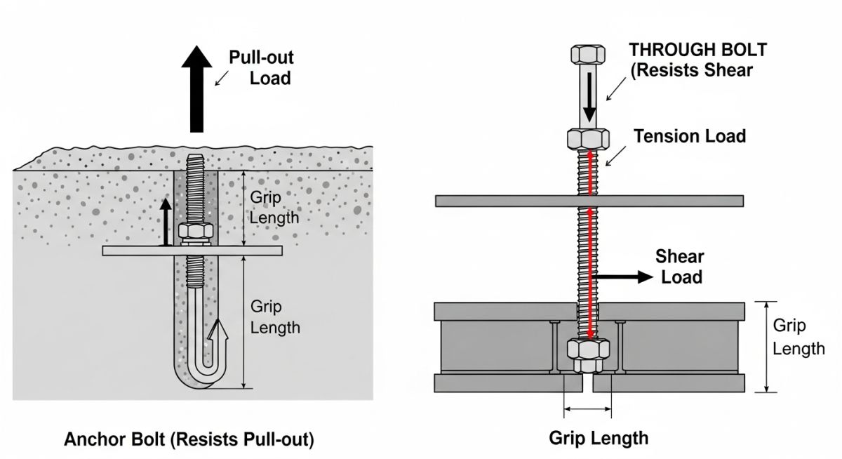
What is a Through Bolt and How Does It Function?
A through bolt is a basic but essential structural fastener that passes completely through two or more members (the joint) and is secured by a nut on the opposite side. Unlike a tap bolt that is threaded directly into one member, the through bolt's integrity relies entirely on its ability to clamp the material between the bolt head and the nut.
The fundamental principle behind Through Bolting is the development of a large **Preload** (axial tension) within the bolt shank, which translates to a tremendous **Clamping Force** applied to the joint. This clamping force is what gives the assembly its remarkable strength against sliding or separation, often referred to as a friction-type connection under standards like ASTM F3125.
Mechanical Principles of Through Bolting in Structural Joints
The Crucial Role of Preload (Axial Tension)
The effectiveness of Through Bolting hinges on the controlled application of torque to achieve a specific bolt Preload. This preload tension keeps the joint members compressed together, ensuring that any external shear force applied to the connection is resisted primarily by the **static friction** between the clamped surfaces before the bolt itself is stressed in shear.
Grip Length and Joint Relaxation
The Grip Length—the total thickness of the material being clamped—is an essential factor. A longer grip length generally results in a more elastic joint, which is better at sustaining the preload over time without significant relaxation. This is vital in timber structures or joints with shims, where the material itself may settle or compress after the initial tightening. Engineers use the Torque-Tension relationship to calculate the precise torque needed for the specified bolt material (e.g., ASTM A325).
Load Transfer: Shear vs Tensile Loading
In a well-designed Through Bolting application, the bolt's primary job is to maintain the preload, making the joint's load-carrying capacity a function of friction. However, if the shear force exceeds the friction limit, the joint slips, and the bolt bears the load directly in shear. In applications involving direct tension (pull-apart forces), the bolt shank and its threads carry the full load, making proper material grade selection mandatory.
Industrial Applications of Through Bolting for Maximum Security
Due to its superior strength and inspectability, Through Bolting is the preferred fastening method in environments where failure is not an option. Its use spans from heavy construction to precision machinery mounting.
Heavy Construction: Timber Framing and Steel Connections
- Steel-to-Steel Connections: Used for primary moment and shear connections in steel-frame buildings, often utilizing **high-strength structural fastener assemblies** (bolts, nuts, and washers).
- Mass Timber Framing: Essential for joining glulam beams and heavy timber posts, where the bolt must distribute forces across the entire wooden member. Galvanized bolts are common here for corrosion resistance.
- Base Plate Fixing: Although anchor bolts are common, Through Bolting is sometimes used when fixing to existing structures where full access to the underside (e.g., through a hollow section) is available, offering unparalleled pull-out resistance.
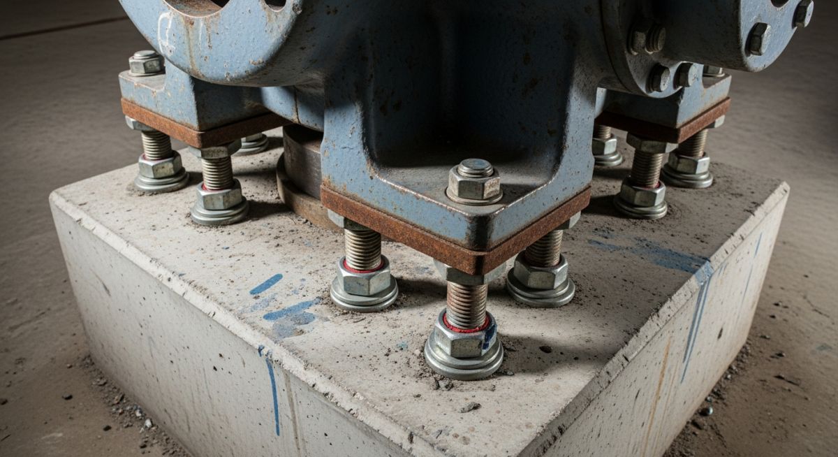
Industrial Machinery: Vibration-Resistant Through Bolting
Machinery and equipment subject to high dynamic loads—such as large motors, pumps, crushers, and conveyors—rely on Through Bolting to maintain alignment. The high preload achieved prevents relative motion, which is the primary cause of fatigue failure and bolt loosening. Special attention is paid to using **Lock Nuts** or **Chemical Thread Lockers** to ensure the nut does not back off under constant vibration.
Automotive Engineering: Chassis and Suspension Integrity
In automotive design, Through Bolting secures safety-critical components like engine mounts, suspension control arms, and major chassis components. These joints are subjected to complex, multi-axial stresses (tension, shear, and bending), making the reliability of a fully clamped connection paramount. These often require precise torque-angle control during installation to guarantee the exact preload specified by the manufacturer.
Technical Selection: Tools and Materials Required for Through Bolting
The execution of secure Through Bolting requires precision tools and correctly matched materials to meet the required design strength.
Fastener Components
ASTM Grade Bolt (e.g., A325, B7), Hex Nut (often heavy hex), and hardened flat washers to distribute the load.
Torque Application Tools
Calibrated Torque Wrenches (hydraulic or manual) or Turn-of-Nut Tensioning Methods (using pneumatic wrenches).
Verification Methods
Skidmore-Wilhelm Tension Testers or Direct Tension Indicators (DTIs) for confirming the achieved preload.
Through Bolting Best Practices: Torque and Preload Standards
Proper execution of Through Bolting follows a strict engineering procedure to ensure the design shear and tensile loads are met.
- Verification of Grip Length: Ensure the bolt length is correct to allow at least 2 threads to protrude beyond the nut after final tensioning.
- Lubrication: Always lubricate threads and bearing surfaces to ensure the torque is converted efficiently into axial tension (preload) rather than wasted on friction.
- Snug-Tightening: Initially tighten all bolts in the pattern to a 'snug-tight' condition (e.g., about 10 percent of final torque) to draw the plies into firm contact.
- Final Tensioning: Apply the final specified torque or rotation (Turn-of-Nut method) to achieve the full, required minimum preload.
Through Bolting Torque-to-Preload Estimator
Estimate the required torque for Through Bolting based on the fundamental T=KDF formula. This calculation is crucial for achieving the correct clamping force (Preload).
Example: Approx. 70 percent of a 1-inch A325 bolt's yield strength.
0.17 for lubricated, 0.20 for non-lubricated is common.
Required Tightening Torque (T)
0.00 Ft-Lbf
Formula: T = K × F × D (Ft-Lbf)
Note: The K-Factor is highly dependent on lubrication, material, and surface finish. Actual field torque must be verified via Skidmore testing to ensure proper preload for Through Bolting security.
Threaded vs. Unthreaded Shank: Bolt Body Diameter in Shear
The positioning of the bolt's threads relative to the shear plane is a critical design choice in high-strength Through Bolting. The two main conditions are **N-Condition** (Threads Not excluded from the shear plane) and **X-Condition** (Threads eXcluded from the shear plane). The X-Condition is always preferred where ultimate strength is required.
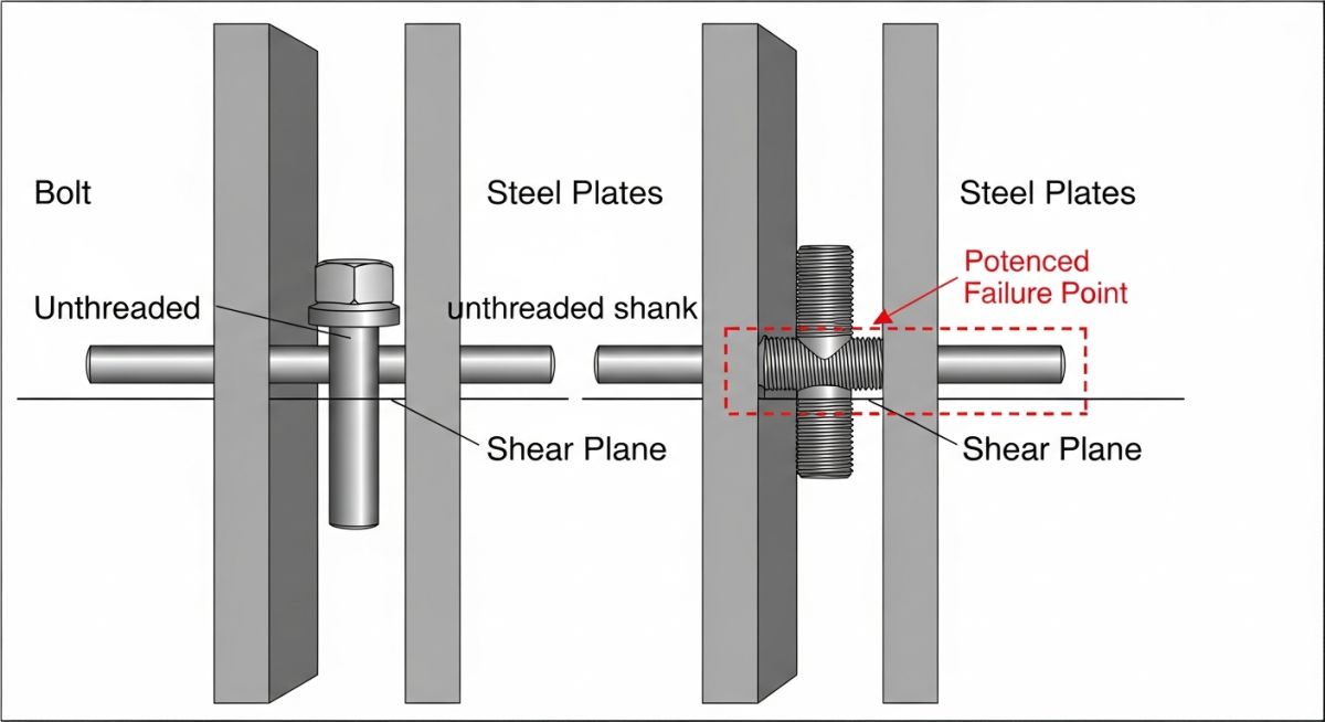
X-Condition (Preferred Shear Design)
In the X-Condition, the unthreaded portion of the bolt's body (the full-diameter shank) bears the shear load. This design is superior for the following reasons:
- Maximum Shear Area: The full nominal diameter of the bolt is used, maximizing the cross-sectional area and thus the **shear strength** of the fastener.
- Stress Concentration: The smooth shank eliminates the stress risers and notch effects inherent to the thread root, preventing premature fatigue failure under cyclic shear loading.
- AISC Standards: Structural codes often permit higher allowable shear stresses when the threads are excluded from the shear plane.
N-Condition (Reduced Shear Design)
The N-Condition occurs when the threads fall into the shear plane. While sometimes unavoidable, it introduces significant compromises in performance:
The effective area resisting shear is the area at the thread root (At), which is significantly smaller than the nominal area (Ab) of the shank. This reduction can be up to 25 percent.
The engineer must calculate the precise length of the bolt required for the specific **Grip Length** and thread length, ensuring the connection is designed for the maximum possible strength, which is the X-Condition.
Don't miss this video related to Through Bolting

Summary: Master Piping Engineering with our complete 125+ hour Certification Course: ......
Case Study: Using Through Bolting to Secure a Gantry Crane Rail to an Existing Concrete Slab
A shipyard expansion project in 2026 required the installation of a new heavy-lift gantry crane. The existing foundation was a 3-foot thick concrete-filled steel beam structure, making standard wedge-type anchor bolts inadequate for the highly dynamic, cyclic, and lateral loads imposed by the moving crane. The engineer's solution was to specify a full Through Bolting system for the rail mounting plates.
Design Challenge and Data
- • Load Type: High Shear, High Dynamic/Cyclic (Cyclic Fatigue)
- • Base Structure: Concrete-filled Steel I-Beam (36 inches deep)
- • Fastener Specification: 1 1/4 inch ASTM F3125 Grade A325 Structural Bolts
The Through Bolting Solution
The engineering design mandated drilling clearance holes completely through the 36-inch deep structure. A specialized 40-inch long **ASTM A325 structural bolt** was used, secured with a heavy hex nut and washer on the underside of the steel beam.
This setup allowed the bolts to be tensioned to the full specified preload of 56,000 Lbf. The resulting clamping force ensured the rail plates resisted the maximum lateral crane forces through pure friction, entirely eliminating the risk of anchor pull-out failure common in heavy, dynamic applications. The **Grip Length** was approximately 38 inches.
Key Lessons Learned
1. Inspectability: The ability to visually confirm the presence of the nut and washer and re-torque the system from the opposite side provided a crucial safety advantage over blind anchor systems.
2. Tension Verification: The final torque was verified using **Direct Tension Indicators (DTIs)** under the bolt head, providing an auditable quality assurance process for the entire Through Bolting system.
Critical Engineering Differences: Anchor Bolts vs Through Bolting
The table below provides a concise comparison of when to select a blind embedment anchor versus a fully accessible Through Bolting connection.
| Feature | Anchor Bolt System | Through Bolting System |
|---|---|---|
| Load Resistance Mechanism | Friction/Mechanical Interlock or Chemical Bond (Pull-out) | Axial Preload (Clamping Force/Friction) |
| Suitability for Dynamic Loads | Poor (Subject to pull-out failure and fatigue in concrete) | Excellent (Joint rigidity resists motion) |
| Inspectability & Re-tensioning | Difficult/Impossible to inspect embedment depth | Fully Visible; can be re-torqued and verified from both sides |
| Required Access | Access to one side only | Access to both sides of the joined material |
Frequently Asked Questions
Why is lubrication important when applying torque to through bolting assemblies?
What is the purpose of a Direct Tension Indicator (DTI) washer in through bolting?
How is shear load transferred in a bolted joint using the grip length?
Conclusion: Future Trends in High-Strength Fastening
The reliability of a structural connection often comes down to the integrity of its fasteners. Through Bolting, while sometimes more complex to install than other methods due to the required access, remains the gold standard for high-strength, fatigue-resistant joints. Its predictable load transfer mechanism, coupled with modern verification tools like DTIs, makes it the foundation for safety-critical applications in every industrial sector.
As structural codes like ASTM F3125 continue to evolve, the emphasis remains on verifiable preload. Engineers must move beyond simple torque application and focus on achieving the necessary tension across the **Grip Length** to ensure the connection functions as a friction-type joint for the service life of the structure in 2026 and beyond.
📚 Recommended Resources: Through Bolting
Read these Guides


Related posts:
![High-grade industrial Wing Nut Types and Applications for mechanical assemblies.]()
Wing Nut Types and Applications: The 2026 Engineering Guide
![Industrial Monorail Crane Systems installed in a modern manufacturing plant 2026.]()
Monorail Crane Systems: Design, Types & 2026 Standards Guide
![Lead engineer performing a Factory Acceptance Test FAT on an industrial skid system 2026]()
Factory Acceptance Test FAT: The 2026 Engineering Guide to Zero-Defect Delivery
![Professional engineering workspace showing a Basis of Design document layout for a 2026 project.]()
Basis of Design: How to Write a BOD for Engineering Projects in 2026
![Industrial Flare Knockout Drum Sizing and installation in a refinery relief system.]()
Flare Knockout Drum Sizing: Design & API 521 Standards (2026 Guide)
![Advanced Reboiler Control Systems in a modern petrochemical refinery 2026.]()
Reboiler Control Systems: Engineering Guide to Precision Control 2026


