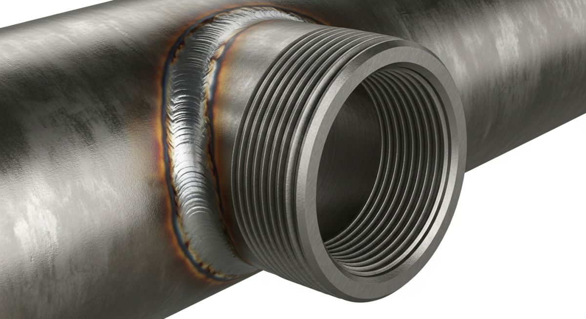
🛠️ EPCLAND WORKSPACE CONTROL PANEL ⚠️ DELETE THIS ENTIRE CONTAINER BOX BEFORE PUBLISHING THE BLOG POST Hero Image: Purpose: To visually introduce a threadolet fitting welded onto a run pipe, showing its threaded branch connection clearly. Description: A high-quality, close-up 3D render of a forged steel threadolet fitting welded onto a larger run pipe, highlighting the internal female threads and the bevel for welding. SEO Alt Text: A forged steel threadolet fitting welded to a main run pipe showing internal threads. Image Slug: forged-steel-threadolet-fitting-on-pipe Filename URL: https://epcland.com/wp-content/uploads/2026/06/forged-steel-threadolet-fitting-on-pipe.jpg Technical Infographic: Purpose: To illustrate the key dimensions of a threadolet fitting for engineering reference. Description: A technical 2D engineering drawing of a threadolet fitting cross-section, with labeled dimension parameters like Height, Thread Size, and Outside Diameter. SEO Alt Text: Technical dimension drawing of a threadolet fitting with labeled parameters. Image Slug: threadolet-fitting-dimensions-technical-drawing Filename URL: https://epcland.com/wp-content/uploads/2026/06/threadolet-fitting-dimensions-technical-drawing.jpg Meta Data: Focus Keyword: threadolet fitting Title: What is a Threadolet Fitting? Ultimate Guide to Threadolet Dimensions Slug: threadolet-fitting-dimensions Meta Description: Learn what a threadolet fitting is, how it works, and explore standard threadolet dimensions for piping systems. Tags: threadolet fitting, threadolet dimensions, olet fittings, branch connection, piping engineering, threaded outlet Author: Atul Singla | Piping Engineering Expert | Updated: May 2026 What is a Threadolet Fitting? Threadolet Dimensions and Engineering Guide Threadolet Fitting: A threadolet fitting is an integrally reinforced branch connection used to join a threaded branch pipe to a larger run header at a 90-degree angle. This forged component complies with ASME B16.11 and MSS SP-97 standards to ensure pressure-temperature ratings match the piping system requirements. Over my 20 years in piping engineering, I have seen many branch connections fail due to poor selection or incorrect installation. When you need a reliable, high-pressure threaded outlet without using a reducing tee, a threadolet is your go-to solution. In my experience, these fittings offer a compact, cost-effective, and structurally sound alternative to traditional branch connections. In this guide, I will break down the design, dimensions, and engineering calculations behind the threadolet fitting. Whether you are designing a high-pressure utility steam line or a chemical process manifold, understanding how these fittings perform under stress is key to maintaining system integrity. Key Takeaways Code Compliance: Threadolets are designed in accordance with MSS SP-97 for integrally reinforced forged branch outlet fittings. Pressure Ratings: Commonly available in 3000# and 6000# classes, matching the ratings of ASME B16.11 threaded fittings. Space Savings: They eliminate the need for run-pipe cutting and reducing tees, significantly reducing the footprint of the piping manifold. Structural Integrity: The forged body provides inherent reinforcement, eliminating the need for additional reinforcing pads. Interactive Engineering Quiz EPCLAND Portal Question 1 of 3 Which standard governs the design, dimensions, and manufacturing of integrally reinforced forged branch outlet fittings like Threadolets, and what are their standard pressure class ratings? ASME B16.9; Class 2000 and Class 3000 MSS SP-97; Class 3000 and Class 6000 ASME B16.11; Class 150 and Class 300 API 6D; Class 900 and Class 1500 Next Question → Question 2 of 3 How are the base contours of Threadolets manufactured and specified to accommodate various run pipe diameters under MSS SP-97? Each Threadolet is custom-machined to a single exact run pipe diameter; a 2" Threadolet for a 12" run cannot be used on a 14" run. Threadolets are manufactured with flat bases only, and the welder must grind the contour to fit the run pipe during installation. Threadolets are manufactured in consolidated run-size ranges where the base contour fits a range of run pipe diameters within acceptable code tolerances. The base contour is standardized to fit only Schedule 40 run pipes, requiring transition rings for Schedule 80 or higher. Next Question → Question 3 of 3 Which ASME standard governs the internal threads of a Threadolet, and what is a critical design consideration regarding thread engagement and fitting geometry? ASME B1.20.1; the thread depth must be deep enough to allow the male pipe to bottom out against the run pipe wall. ASME B1.1; the threads are straight unified national fine (UNF) to prevent leakage under high vibration. ASME B1.20.1; the fitting design must ensure that when the male threaded pipe is fully engaged, it does not obstruct the flow or penetrate past the crotch of the run pipe. ASME B16.25; the threads are buttress threads designed to withstand high axial thrust loads. 🎉 Quiz Completed! You have passed the engineering review criteria. How a Threadolet Fitting Performs Under High Pressure Threadolet Branch Connection: A threadolet fitting functions as an integrally reinforced branch outlet that reduces stress concentration at the run pipe opening by distributing mechanical loads across its forged body. This design eliminates the need for wrapper plates or saddle reinforcements in high-pressure piping networks. A threadolet is part of the "olet" family of fittings, which includes weldolets, sockolets, and elbolets. It features a run-side contour that matches the outside diameter of the header pipe, and a female threaded outlet on the branch side. The branch connection is made by welding the contoured base of the threadolet to the run pipe, and then screwing the branch pipe into the threaded outlet. ASME B31.3 Area Replacement Calculations When you cut a hole in a run pipe to attach a branch, you weaken the pipe's pressure-containing capability. To compensate for this, ASME B31.3 Section 304.3.3 requires that the metal area removed by the opening must be replaced by excess metal in the header wall, branch wall, and the weld metal. Let us walk through a real-world engineering calculation to see how this works. Sample Calculation Parameters: Header Pipe: 8-inch Schedule 40 (Carbon Steel ASTM A106 Gr. B) Header Outside Diameter (D): 219.1 mm Header Nominal Wall Thickness (Th): 8.18 mm Design Pressure (P): 4.0 MPa Design Temperature: 100°C Allowable Stress (S): 138 MPa Joint Quality Factor (E): 1.0 Branch Connection: 1.5-inch Threadolet (3000# rating) Step 1: Calculate the required thickness of the header pipe (t) under internal pressure: t = (P * D) / (2 * (S * E + P * Y)) t = (4.0 * 219.1) / (2 * (138 * 1.0 + 4.0 * 0.4)) t = 876.4 / (2 * (138 + 1.6)) t = 876.4 / 279.2 = 3.14 mm Step 2: Calculate the required reinforcement area (A1): A1 = t * d1 Where d1 is the finished diameter of the branch opening (approx. 48.3 mm for a 1.5-inch branch). A1 = 3.14 mm * 48.3 mm = 151.66 mm² Because the threadolet is manufactured to MSS SP-97 standards, the manufacturer has already designed the forged body to provide 100% area replacement. The heavy forged wall of the threadolet provides a reinforcement area (A2) that far exceeds the required 151.66 mm², making manual reinforcement calculations unnecessary for standard applications. Field Warning: Thread Engagement and Galling In my experience, many field failures occur because installers over-tighten stainless steel branch pipes into carbon steel threadolets without proper lubrication. This leads to thread galling and micro-cracks. Always use a high-quality thread sealant or PTFE tape rated for the process fluid, and adhere to the specified torque limits. Standard Threadolet Dimensions (3000# and 6000#) Threadolet Dimension Standards: Threadolet dimensions are standardized under MSS SP-97, which defines the height, outlet diameter, and thread specifications for forged branch connections. These dimensions ensure that the fitting can withstand the rated pressure of the corresponding pipe schedule. The table below outlines the standard dimensions for Class 3000# and Class 6000# threadolets. Note that the height (A) is measured from the run pipe surface to the top of the threaded outlet. NPS Branch Size (in) Class Rating Height - A (mm) Outlet Dia - F (mm) Thread Type (NPT) Approx. Weight (kg) 1/2" 3000# 25.4 31.8 1/2-14 NPT 0.14 3/4" 3000# 27.0 38.1 3/4-14 NPT 0.23 1" 3000# 33.3 47.6 1-11.5 NPT 0.41 1-1/2" 3000# 38.1 65.1 1.5-11.5 NPT 0.82 2" 3000# 38.1 76.2 2-11.5 NPT 1.13 1/2" 6000# 31.8 38.1 1/2-14 NPT 0.27 1" 6000# 39.7 57.2 1-11.5 NPT 0.77 Technical Mapping & Specifications Matrix Parameter Specification / Standard Material Grades Application Scope Design Standard MSS SP-97 ASTM A105, A182, A350 Integrally reinforced forged branch outlets Thread Standard ASME B1.20.1 N/A Taper pipe threads (NPT) Pressure Class ASME B16.11 Carbon, Stainless, Alloy 3000# and 6000# ratings Welding Code ASME Section IX WPS / PQR Qualified Full penetration groove welds Essential Threadolet Fitting Installation Verification Checklist Threadolet Installation Quality Control: Quality control for threadolet installation requires systematic verification of fit-up gap, thread engagement, and weld profile to prevent joint failure. These checks ensure compliance with ASME B31.3 welding procedures and prevent thread galling during assembly. Before releasing a piping system for pressure testing, I always run through a strict verification protocol on site. Below is the checklist I use to ensure every threadolet fitting is installed to code. Site Verification Checkpoints 1. Contour Match Verification Ensure the contoured base of the threadolet matches the outside diameter of the run pipe. A mismatch will cause uneven weld gaps and potential root defects. 2. Root Gap and Fit-Up Verify a root gap of 1.6 mm to 2.4 mm is maintained before tack welding. This ensures full penetration of the weld root. 3. Thread Protection During Welding Ensure a temporary plug or nipple is inserted into the threadolet during welding to protect the internal threads from weld spatter and thermal distortion. 4. Weld Profile Inspection Inspect the final weld profile. It must be a full-penetration groove weld with a smooth transition to the run pipe, complying with ASME B31.3 Figure 328.5.4D. 5. Thread Gauging Post-Weld After the weld has cooled completely, run an NPT thread gauge through the fitting to verify that thermal contraction has not distorted the thread pitch. Field Case Study: Real-World Application Field Case Study: Real-World Application The Problem: Recurring Leaks on Steam Header Outlets At a petrochemical plant in Texas, a 12-inch high-pressure steam header (operating at 3.5 MPa and 240°C) experienced recurring leaks at several 1-inch threaded branch connections. The original design utilized standard half-couplings welded to the header. Due to thermal cycling, the high stress concentration at the sharp corners of the half-couplings caused fatigue cracking along the heat-affected zone (HAZ) of the weld. The Solution & Outcome: As the lead piping consultant, I recommended replacing the half-couplings with forged ASTM A105N Class 3000# threadolet fittings. The contoured base of the threadolet distributed the thermal expansion stresses evenly across the header wall. We also implemented a strict pre-heating procedure (150°C) before welding to prevent hydrogen cracking. Following the upgrade, the system underwent 100% dye penetrant testing and a hydrostatic test at 5.25 MPa. Over the next three years of continuous operation, zero leaks or micro-cracks were detected, saving the plant an estimated 120,000 in unscheduled maintenance downtime. My recommendation for any high-temperature or cyclic service is to avoid half-couplings entirely. The integral reinforcement of a threadolet is well worth the minor increase in initial material cost. Frequently Asked Engineering Questions Threadolet Engineering FAQ: This technical FAQ addresses common design, selection, and installation questions regarding threadolet fittings in industrial piping systems. All answers align with ASME B31.3 and MSS SP-97 standards. What is the difference between a threadolet and a weldolet? The primary difference lies in the branch connection method. A weldolet has a beveled end designed for a butt-weld connection to the branch pipe, whereas a threadolet has a female threaded (NPT) outlet designed for a screwed connection. Both utilize a contoured base for welding to the run pipe. Can a threadolet be used in high-pressure hydrogen service? Yes, but with strict limitations. In hydrogen service, threaded connections are prone to micro-leakage. While the forged body of the threadolet is structurally rated for high pressures, I recommend seal-welding the threaded joint or opting for a weldolet to ensure a completely hermetic seal. How do I select the correct run size for a threadolet? Threadolets are manufactured to fit a range of run pipe sizes. For example, a single 1-inch threadolet might be contoured to fit run pipes from 3 inches to 6 inches in diameter. Always check the manufacturer's catalog or MSS SP-97 consolidated run size charts to ensure a proper fit. What is the pressure rating of a 3000# threadolet? A Class 3000# threadolet is designed to match the pressure-temperature rating of Schedule 80 (Extra Strong) pipe. It is not rated for a flat 3000 psi across all temperatures; instead, its pressure rating decreases as the operating temperature increases, in accordance with ASME B16.11. Is post-weld heat treatment (PWHT) required for threadolets? PWHT depends on the run pipe material and wall thickness, not the threadolet itself. If the run pipe is carbon steel with a wall thickness exceeding 19 mm (per ASME B31.3), or if it is a low-alloy steel like P11 or P22, PWHT is mandatory to relieve residual welding stresses. Can I use a threadolet on a curved elbow? No, standard threadolets are contoured for straight run pipes. If you need a threaded branch connection on an elbow, you must use an elbolet, which is specifically forged with a double-contour base to match the complex geometry of a long-radius or short-radius elbow.